
1. Ifihan
This manual provides comprehensive instructions for the installation, operation, and maintenance of your Chieftec Mesh MidiTower LCX-01SL-SL-B PC case. Please read this manual thoroughly before beginning any installation to ensure proper setup and safe handling of your components.
2. Ọja Ipariview
The Chieftec Mesh MidiTower LCX-01SL-SL-B is a versatile computer chassis designed for ATX 2.0 power supplies and Micro ATX motherboards. It features a mesh design for optimal airflow and includes multiple drive bays for storage and optical devices. The case provides convenient front panel connectivity with two USB 2.0 ports and two USB 3.0 ports.

Aworan: Ti abẹnu view of the Chieftec Mesh MidiTower LCX-01SL-SL-B PC case, highlighting the drive bays and general layout.
3. Eto ati fifi sori
3.1 Awọn iṣọra aabo
- Nigbagbogbo ge asopọ ipese agbara lati inu iṣan ogiri ṣaaju fifi sori ẹrọ tabi yiyọ awọn paati eyikeyi kuro.
- Wọ okun ọwọ-atako-aimi lati ṣe idiwọ isọjade elekitirotatiki (ESD) ibajẹ si awọn paati ifura.
- Mu awọn paati farabalẹ lati yago fun ibajẹ ti ara.
3.2 Nsii ọran naa
- Gbe ọran naa sori alapin, dada iduroṣinṣin.
- Locate and remove the thumbscrews or standard screws securing the side panel(s) at the rear of the case.
- Gently slide the side panel(s) backward and lift them away from the chassis.
3.3 Fifi sori modaboudu
- Install the I/O shield into the opening at the rear of the case.
- Align the motherboard with the pre-installed standoffs. If necessary, install additional standoffs according to your motherboard's form factor.
- Carefully place the motherboard onto the standoffs, ensuring the I/O ports align with the I/O shield.
- Fi àwọn skru tí a pèsè so mọ́ motherboard náà. Má ṣe fún un ní okun jù.
3.4 Fifi sori ẹrọ Ipese Agbara
- Position the ATX 2.0 power supply unit (PSU) in the designated bottom-mount bay.
- Align the screw holes on the PSU with those on the case's rear panel.
- Secure the PSU with the provided screws.
3.5 Lile wakọ sori
The Chieftec Mesh MidiTower features tool-less drive trays for easy installation of 3.5-inch hard drives.
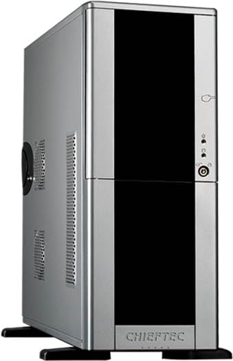
Image: Installation of a 3.5-inch hard drive into a tool-less drive bay.
- Gently pull out an empty drive tray from the drive cage.
- Flex the sides of the tray to fit the 3.5-inch hard drive, aligning the screw holes on the drive with the pins on the tray.
- Once the drive is secured in the tray, slide the tray back into the drive cage until it clicks into place.
- Connect the SATA data and power cables to the installed hard drive.
3.6 Optical Drive Installation (5.25-inch bays)
- Remove the desired 5.25-inch bay cover from the front panel.
- Slide the optical drive into the bay from the front of the case until it is flush with the front panel.
- Secure the drive using the provided tool-less clips or screws on both sides.
- Connect the SATA data and power cables to the optical drive.
3.7 Imugboroosi kaadi sori
- Remove the appropriate expansion slot cover(s) from the rear of the case.
- Insert the expansion card (e.g., graphics card, sound card) into the corresponding PCIe slot on the motherboard.
- Secure the card with a screw or the case's retention mechanism.
3.8 USB Management
Lo àwọn ohun tí a gé síta àti àwọn ibi tí a ti so mọ́ ara wọn lẹ́yìn àwo módàbù láti ṣètò àwọn wáyà. Èyí mú kí afẹ́fẹ́ àti ẹwà wọn sunwọ̀n síi.
3.9 Tilekun Ọran naa
- Rí i dájú pé gbogbo àwọn ohun èlò náà wà ní ààbò àti pé gbogbo àwọn okùn tó yẹ ni a so pọ̀.
- Slide the side panel(s) back into place and secure them with the thumbscrews or standard screws.
4. Ṣiṣẹ
Once all internal components are installed and the case is closed, connect your monitor, keyboard, mouse, and other peripherals to the appropriate ports on your motherboard's I/O panel. Connect the power cable to the power supply unit and then to a wall outlet. Press the power button on the front of the case to start your system.
5. Itọju
5.1 Ninu
- Regularly clean dust filters (if present) to maintain optimal airflow.
- Use compressed air to remove dust from inside the case and components. Ensure the system is powered off and unplugged before cleaning.
- Nu ita apoti naa pẹlu asọ rirọ, damp asọ. Yago fun awọn kẹmika lile.
5.2 Afẹfẹ
Ensure the case has adequate clearance around its intake and exhaust vents to allow for proper airflow and cooling of internal components.
6. Laasigbotitusita
6.1 System Ko Power On
- Verify that the power cable is securely connected to both the power supply and the wall outlet.
- Ensure the power switch on the back of the power supply is in the 'ON' position.
- Check that the front panel power button cable is correctly connected to the motherboard.
- Confirm all internal power connections (24-pin ATX, 8-pin CPU, PCIe power) are firmly seated.
7. Awọn pato
| Ẹya ara ẹrọ | Sipesifikesonu |
|---|---|
| Orukọ awoṣe | Mesh MidiTower LCX-01SLSLB |
| Nọmba Awoṣe Nkan | LCX-01SL-SL-B |
| Iru Irú | MidiTower |
| Modaboudu Ibamu | Micro ATX |
| Ibamu Ipese Agbara | ATX 2.0 (Bottom Mount) |
| Awọn iwọn (LxWxH) | 21.26 x 8.07 x 20.63 inches |
| Iwọn Nkan | 11.66 iwon |
| Awọn ibudo USB 2.0 | 2 |
| Awọn ibudo USB 3.0 | 2 |
| 5.25 "Wakọ Bays | 4 |
| Ọna Itutu | Afẹfẹ |
| Àwọ̀ | Dudu |
| Ohun elo | Irin |
8. Atilẹyin ọja ati Support
For warranty information and technical support, please refer to the official Chieftec website or contact your local retailer. Warranty terms and conditions may vary by region and product. Keep your proof of purchase for warranty claims.