
1. Ifihan
The Greisinger GIA 2448 is a digital panel meter designed for measuring and visualizing standard signals. This device allows users to select desired measurement ranges via solder bridges, making it versatile for various applications. It supports a wide array of voltage and current inputs, providing clear digital readouts.
This manual provides essential information for the safe and efficient operation of your GIA 2448 panel meter. Please read it thoroughly before installation and use.
2. Alaye Aabo
- Ge asopọ agbara nigbagbogbo ṣaaju fifi sori ẹrọ tabi itọju.
- Awọn oṣiṣẹ ti o peye nikan ni o yẹ ki o ṣe fifi sori ẹrọ ati itọju.
- Rí i dájú pé ẹ̀rọ náà wà ní ààbò láti ọrinrin àti àwọn iwọn otutu tó le koko.
- Do not operate the device if it shows signs of damage.
- Observe all local and national electrical safety regulations.
- The device is designed for professional use only.
3. Eto ati fifi sori
The GIA 2448 is an embedded display unit. Proper installation ensures accurate readings and device longevity.
- Ige nronu: Prepare a panel cutout of 24 x 48 mm for mounting the device.
- Iṣagbesori: Insert the GIA 2448 into the prepared cutout and secure it using the provided mounting clips.
- Ibi ti ina elekitiriki ti nwa: Connect the power supply. The standard voltage supply is 18-29 V/DC, selectable via solder bridge.
- Input Signal: Connect the signal source to the appropriate input terminals.
- Measurement Range Selection: Select the desired measurement range using the solder bridges on the device's circuit board. Refer to the "Operating Instructions" section for available ranges.
- Ìwọ̀n Ìfihàn: The display range can be scaled via solder bridges and a potentiometer for customized visualization.
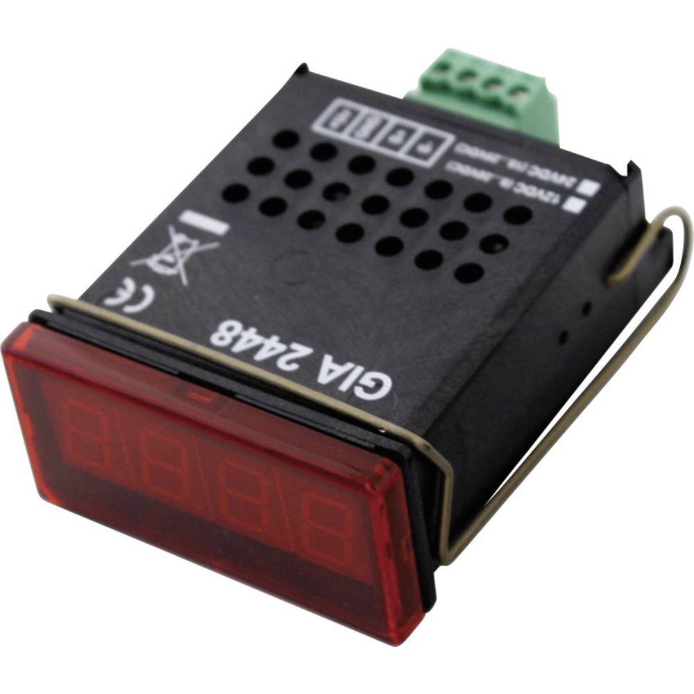
olusin 1: Iwaju view of the Greisinger GIA 2448 Digital Panel Meter. This image shows the compact design and digital display for integration into control panels.
4. Awọn ilana Iṣiṣẹ
The GIA 2448 is designed for straightforward operation once installed and configured.
4.1 Measurement Range Selection
The device supports various standard signal measurement ranges. These are selected by configuring specific solder bridges on the internal circuit board. Ensure power is disconnected before making any changes to the solder bridges.
Available measurement functions include:
- 0 - 20 V
- 0 - 10 V
- 0 - 2 V
- 0 - 1 V
- 0 - 200 mV
- 0 - 20 mA
- 4 - 20 mA
Consult the detailed wiring diagram (not provided in this manual, refer to product packaging or manufacturer's website) for the exact location and configuration of the solder bridges for each range.
4.2 Display Reading
Once powered and configured, the GIA 2448 will display the measured signal value on its digital screen. The display is designed for clear readability.
The display field is scalable via solder bridges and a potentiometer, allowing for custom scaling of the input signal to the displayed value.
5. Itọju
The Greisinger GIA 2448 is designed for low maintenance. Regular cleaning and inspection are recommended.
- Ninu: Nu iwaju nronu pẹlu asọ, damp asọ. Ma ṣe lo abrasive ose tabi epo.
- Ayewo: Lojoojumọ, ṣayẹwo gbogbo awọn asopọ fun wiwọ ati awọn ami ti yiya tabi ibajẹ.
- Iṣatunṣe: While the device is factory calibrated, professional recalibration may be required periodically depending on application and regulatory requirements.
6. Laasigbotitusita
| Isoro | Owun to le Fa | Ojutu |
|---|---|---|
| Ko si ifihan | Ko si ipese agbara tabi vol ti ko tọtage. | Check power connections and ensure voltage is within 18-29 V/DC. |
| kika ti ko tọ | Wrong measurement range selected or incorrect scaling. | Verify solder bridge configuration for the correct measurement range. Adjust display scaling potentiometer if necessary. |
| Display shows "OL" or "Err" | Input signal out of selected range. | Select a higher measurement range or check the input signal source. |
7. Awọn pato
- Awoṣe: GIA 2448
- Iru ọja: Digital Panel Mita
- Mefa (H x W): 24 mm x 48 mm
- Iwọn oni-nọmba: 10 mm
- Kilasi Idaabobo: IP54 (iwaju)
- Iyara Wiwọn: 3 aaya
- Standard Voltage Ipese: 18-29 V/DC (selectable via solder bridge)
- Selectable Measurement Ranges:
- Voltage: 0-20 V, 0-10 V, 0-2 V, 0-1 V, 0-200 mV
- Current: 0-20 mA, 4-20 mA
- Display Field: Scalable via solder bridge and potentiometer
8. Atilẹyin ọja ati Support
For warranty information and technical support, please refer to the official GREISINGER webaaye tabi kan si olupin agbegbe rẹ. Tọju iwe-ẹri rira rẹ bi ẹri rira.
Olupese: GREISINGER
Nọmba awoṣe: 600458 (Internal Reference: 102977-62)
ASIN: B005OJU4LC
Fun iranlọwọ siwaju sii, jọwọ ṣabẹwo si GREISINGER official webojula.