1. Ifihan
The VEMER Logik Micro DW VP888200 is a compact digital daily and weekly timer switch designed for precise management of electrical loads. This device features a modular 1 DIN unit design, an LCD display, and supports up to 20 ON/OFF or impulse programs with a 1-minute resolution. It is ideal for automating various electrical circuits in residential or commercial settings.
2. Alaye Aabo
Please read these safety instructions carefully before installation and operation. Failure to follow these instructions may result in electric shock, fire, or damage to the device.
- Fifi sori ẹrọ itanna: Fifi sori gbọdọ jẹ ṣiṣe nipasẹ onisẹ ina mọnamọna ni ibamu pẹlu gbogbo awọn koodu itanna agbegbe ati ti orilẹ-ede.
- Ge asopọ agbara: Always disconnect power to the circuit at the main breaker before installing, servicing, or removing the device.
- Voltage: Rii daju pe ipese voltage matches the device's specifications (230V AC, 50/60Hz).
- Agbara fifuye: Do not exceed the maximum load capacity of the relay (16A at 250V AC, cos(Φ)=1).
- Ayika: Do not expose the device to moisture, extreme temperatures, or corrosive environments. The operating temperature range is -10°C to +50°C.
- Idaabobo: The device has an IP40 protection rating, meaning it is protected against solid objects larger than 1mm but not against liquids.
3. Ọja Ipariview
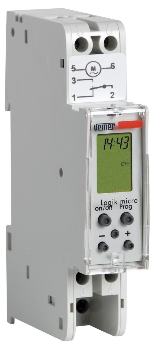
The VEMER Logik Micro DW is a compact digital timer switch designed for DIN rail mounting. It features a clear LCD display for programming and status indication.
3.1. Physical Dimensions and Wiring Diagram
The following image illustrates the front and side dimensions of the Logik Micro DW, along with its electrical wiring diagram.
Apejuwe aworan: This image displays three views of the VEMER Logik Micro DW VP888200. On the left, the "Vista frontale" (Front view) shows the device's height as 88mm and width as 18mm. In the center, the "Vista laterale" (Side view) indicates a depth of 60mm and a DIN rail clip height of 45mm. On the right, the "Schema" (Wiring Diagram) illustrates the electrical connections: L (Line) and N (Neutral) inputs, and the relay contacts labeled 1, 2, 3, 4, 5, 6. The diagram shows the internal relay switching between contacts for load control.
- Iwaju View: Height 88mm, Width 18mm.
- Apa View: Depth 60mm, DIN rail clip height 45mm.
- Aworan atọka:
- L (Line) and N (Neutral): Ipese agbara igbewọle.
- Awọn olubasọrọ Ifiranṣẹ: The device features a single changeover relay (1 NO/NC contact). Connect the load according to the desired switching configuration.
5. Awọn ilana Iṣiṣẹ
The Logik Micro DW allows for daily and weekly programming of electrical loads.
5.1. Àwọn Ìgbékalẹ̀ Ìṣètò
- Eto ojoojumọ: Programs repeat every day at the same set time.
- Eto Ọsẹ: Programs can be set for specific days of the week or groups of days.
5.2. Ṣíṣeto Àwọn Ètò TÍTÀN/PÁÀBÍ
The device supports up to 20 ON/OFF programs. Each program consists of an ON time and an OFF time.
- Tẹ Ipo Eto: Press the designated button (e.g., "PROG" or "SET") to enter the programming menu.
- Select Program Number: Choose an available program slot (e.g., P1, P2, ..., P20).
- Ṣètò Àkókò Tí Ó Ń SÍ: Input the desired time for the load to switch ON.
- Àkókò Ṣíṣí: Input the desired time for the load to switch OFF.
- Select Days: Choose the days of the week for the program to be active (e.g., Mon-Fri, Sat-Sun, or specific days).
- Save Program: Confirm and save the program. Repeat for additional programs.
The programming resolution is 1 minute, allowing for precise control.
5.3. Impulse Programming
The device also supports impulse programming, where the relay briefly activates for a set duration.
- Tẹ Ipo Eto: Wọle si akojọ aṣayan siseto.
- Select Impulse Program: Choose an impulse program slot.
- Set Impulse Time: Define the time when the impulse should occur.
- Set Impulse Duration: Specify how long the relay should remain active (e.g., 1-59 seconds).
- Select Days: Choose the days for the impulse program.
- Save Program: Jẹrisi ati fipamọ.
5.4. Yiyọ Afowoyi
The device typically includes a manual override function to temporarily switch the load ON or OFF independently of the programmed schedule. Consult the device's physical buttons or display menu for this function.
6. Itọju
6.1. Ninu
To clean the device, gently wipe the exterior with a soft, dry cloth. Do not use abrasive cleaners, solvents, or spray liquids directly onto the device.
6.2. Battery Reserve
The Logik Micro DW features a rechargeable lithium battery that provides a power reserve of approximately 3 years. This reserve maintains the time and programmed settings during power outages. The relay will only switch in the presence of mains power.
- The battery is internal and not user-replaceable.
- Regular operation with mains power will keep the battery charged.
9. Atilẹyin ọja & Atilẹyin
VEMER products are manufactured to high-quality standards. For specific warranty terms and conditions, please refer to the documentation provided with your purchase or visit the official VEMER webojula.
For technical support, troubleshooting assistance beyond this manual, or service inquiries, please contact VEMER customer support through their official channels. Ensure you have your product model number (VP888200) and purchase details available when contacting support.
Official VEMER Webojula: www.vemer.it
