
1. Ifihan
This manual provides detailed instructions for the safe and effective operation of the Meco 2250-HZ Auto Digital Clamp Meter. This device is designed for measuring various electrical parameters, including AC/DC voltage, AC current, frequency, continuity, and diode testing. Please read this manual thoroughly before use and retain it for future reference.
2. Alaye Aabo
Always observe standard safety precautions when working with electrical circuits. Failure to do so may result in injury or damage to the meter. This meter is designed with over-voltage protection up to 200V DC and AC Peak. However, exercise caution.
- Ma ṣe gbiyanju lati wiwọn voltagawọn iṣan omi tabi awọn sisan omi ti o kọja awọn opin ti o pọju ti a sọ.
- Ensure the test leads are in good condition and properly connected before making measurements.
- Do not operate the meter if it appears damaged or if the battery cover is not securely closed.
- Avoid using the meter in wet environments or in the presence of explosive gases or dust.
- Always disconnect power to the circuit before connecting or disconnecting test leads, especially for current measurements.
3. Ọja Ipariview
The Meco 2250-HZ Auto Digital Clamp Meter features a robust design for reliable performance. Familiarize yourself with the components shown below.
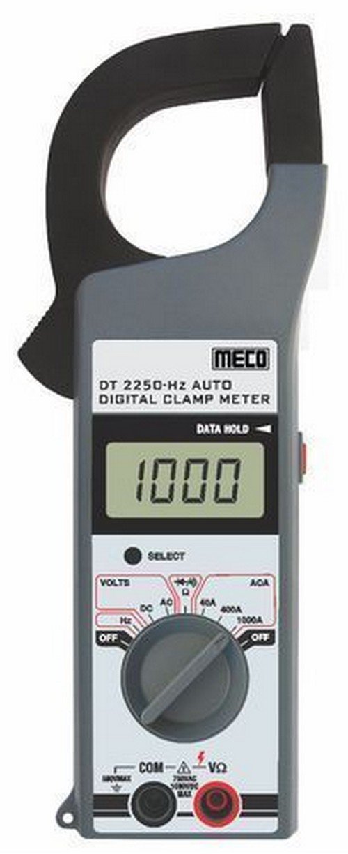
Nọmba 1: Iwaju view of the Meco 2250-HZ Auto Digital Clamp Meter. This image displays the clamp jaw at the top, the LCD screen showing '1000', the function dial, and the input terminals at the bottom. The 'SELECT' and 'DATA HOLD' buttons are visible next to the display.
Awọn eroja pataki:
- Clamp Ẹrẹ: A lo fun wiwọn agbara AC ti ko ni ifọwọkan.
- Ifihan LCD: 3¾ digit liquid crystal display with a maximum reading of 3999. Shows measurement values, polarity, overrange indication (OL or -OL), and low battery indication.
- Ṣiṣe ipe iṣẹ: Rotary switch to select measurement functions (OFF, Volts DC/AC, Hz, ACA 40A/400A/1000A).
- Bọtini Yan: Used to switch between DC and AC voltage modes, or other sub-functions within a dial setting.
- Bọ́tìnì DÍDÁ DÁTÀ MÚ: Didi kika lọwọlọwọ lori ifihan. Tẹ lẹẹkansi lati tu silẹ.
- Àwọn Ibùdó Ìwọlé (COM, VΩ): Fun sisopọ awọn itọsọna idanwo fun voltage, resistance, continuity, and diode measurements.
4. Eto
4.1 Fifi sori batiri
The Meco 2250-HZ Auto Digital Clamp Meter requires batteries for operation. Batteries are not included with the product. To install or replace batteries:
- Rí i dájú pé mita náà ti pa.
- Wa yara batiri ni ẹhin mita naa.
- Lo screwdriver lati ṣii ideri iyẹwu batiri naa.
- Insert the required batteries, observing correct polarity (+ and -).
- Rọpo ideri kompaktimenti batiri ki o ni aabo pẹlu dabaru.
A low battery indication will appear on the display when the battery voltage is low, signaling the need for replacement.
5. Awọn ilana Iṣiṣẹ
5.1 Gbogbogbo isẹ
- Turn the function dial to the desired measurement setting.
- Connect test leads to the appropriate input terminals (COM and VΩ) for voltage, resistance, continuity, or diode tests.
- For current measurements, use the clamp jaw around a single conductor.
- Tẹ awọn Yan button to toggle between AC/DC modes or other sub-functions if available for the selected range.
- Tẹ awọn DATA idaduro bọ́tìnì láti dì kíkà tó wà lórí ìbòjú náà. Tẹ̀ lẹ́ẹ̀kan síi láti tú u sílẹ̀.
5.2 AC / DC Voltage Idiwon
- Set the function dial to the "VOLTS" position.
- Connect the black test lead to the COM terminal and the red test lead to the VΩ terminal.
- Tẹ awọn Yan button to choose between AC or DC voltage measurement. The display will indicate "AC" or "DC".
- So awọn itọsọna idanwo ni afiwe si Circuit tabi paati labẹ idanwo.
- Ka voltage iye lori ifihan LCD.
5.3 AC Wiwọn lọwọlọwọ (Clamp)
- Set the function dial to the desired AC current range (40A, 400A, or 1000A).
- Ṣii clamp ẹnu nípa títẹ ohun tí ń fa ìfàsẹ́yìn náà.
- Fi adarí kan ṣoṣo ti Circuit naa sinu cl naaamp àgbọ̀n. Rí i dájú pé àgbọ̀n náà ti sé pátápátá.
- Ka iye agbara AC lori ifihan LCD.
5.4 Frequency (Hz) Measurement
- Set the function dial to the "Hz" position.
- Connect the black test lead to the COM terminal and the red test lead to the VΩ terminal.
- Connect the test leads in parallel to the circuit where frequency needs to be measured.
- Read the frequency value in Hertz (Hz) on the LCD display.
5.5 Audible Continuity Check
- Set the function dial to the continuity/diode symbol (often shared with resistance).
- Connect the black test lead to the COM terminal and the red test lead to the VΩ terminal.
- Touch the test probes across the component or circuit to be tested.
- Tí ìtẹ̀síwájú bá wà (ìdènà díẹ̀), mita náà yóò mú ìró ohùn tí a lè gbọ́ jáde.
5.6 Idanwo Diode
- Set the function dial to the continuity/diode symbol.
- Connect the black test lead to the COM terminal and the red test lead to the VΩ terminal.
- Connect the red test lead to the anode of the diode and the black test lead to the cathode. The display will show the forward voltage ju.
- Reverse the test leads. The display should show "OL" (overload) for a good diode.
6. Itọju
6.1 Ninu
Nu mita c naaasing pẹlu ipolowoamp cloth and a mild detergent. Do not use abrasives or solvents. Keep the display clean and dry.
6.2 Batiri Rirọpo
Refer to Section 4.1 for battery installation and replacement instructions. Replace batteries promptly when the low battery indicator appears to ensure accurate readings.
7. Laasigbotitusita
| Isoro | Owun to le Fa | Ojutu |
|---|---|---|
| Mita ko ni agbara lori. | Awọn batiri ti o ku tabi ti ko tọ ti fi sori ẹrọ. | Ṣayẹwo polarity batiri ki o rọpo awọn batiri ti o ba jẹ dandan. |
| "OL" or "-OL" displayed. | Overrange condition; measurement exceeds meter's range. | Select a higher range or ensure the measured value is within the meter's capabilities. |
| Awọn kika ti ko pe. | Low battery, poor test lead connection, or incorrect function selection. | Replace batteries, ensure secure connections, verify function dial setting. |
| No audible beep during continuity test. | Ṣíṣí Circuit tàbí resistance gíga. | Verify the circuit is closed and resistance is low enough for continuity. |
8. Awọn pato
| Ẹya ara ẹrọ | Ẹ̀kúnrẹ́rẹ́ |
|---|---|
| Ifihan | 3¾ digit LCD, max reading 3999 |
| Polarity | Automatic, negative polarity indication |
| Overrange Atọka | "OL" or "-OL" displayed |
| Tolesese Zero | Laifọwọyi |
| Igbesi aye batiri | 200 wakati aṣoju |
| Lori Voltage Idaabobo | 200V DC and AC Peak |
| Audible Continuity Check | Bẹẹni |
| Idanwo Diode | Bẹẹni |
| Itọkasi Batiri Kekere | Bẹẹni |
| Iwọn Nkan | 600 g (1.32 iwon) |
| Ọja Mefa | 21 x 13 x 6 cm |
| Ohun elo | Ṣiṣu |
| Olupese | Meco Instruments |
9. Atilẹyin ọja ati Support
For warranty information or technical support, please contact the retailer or the manufacturer, Meco Instruments, directly. Keep your purchase receipt as proof of purchase.