
1. Ifihan
This manual provides comprehensive instructions for the installation, operation, and maintenance of the Datakom DKM-0224 Alarm Annunciator. The DKM-0224 is a 24-channel alarm annunciator designed for use in generator sets and industrial automation systems, providing visual and audible alerts for various operational conditions.
It features optically isolated digital inputs with noise-cancelling filters and adjustable detection delay. The module includes 3 relay outputs for horn, bell, and internal failure, and supports RS-485 Modbus RTU communication for remote monitoring.

Nọmba 1.1: Front panel of the Datakom DKM-0224 Alarm Annunciator, showing 24 alarm channels with red/green LEDs, and control buttons for Reset, Horn, Test, and Acknowledge (ACK).
2. Key Awọn ẹya ara ẹrọ
- 24 optically isolated digital inputs with noise-cancelling filters.
- Adjustable detection delay for inputs (2ms to 500ms).
- 3 configurable relay outputs (Horn, Bell, Internal Failure) rated at 5A/250V.
- Bicolor (red/green) LED indicators for each channel, indicating alarm status.
- Front panel pushbuttons for alarm acknowledgment, reset, and test.
- RS-485 Modbus RTU communication for remote monitoring and control.
- Wide ipese voltage range: 19-150VDC or 85-305VAC.
- Apẹrẹ fun iṣagbesori nronu iwaju.
- Generator protection features with built-in alarms and warnings.
3. Eto ati fifi sori
3.1 Panel iṣagbesori
The DKM-0224 is designed for front panel mounting. Ensure adequate space for installation and ventilation.

Nọmba 3.1: Panel cut-out dimensions (140mm x 140mm) and side view with minimum depth requirement (55mm) for the DKM-0224.
The required panel cut-out dimensions are 140mm x 140mm. The minimum depth required behind the panel is 55mm.
3.2 Awọn isopọ onirin
Tọkasi si ẹhin view diagram for detailed wiring instructions. All connections should be made by qualified personnel.
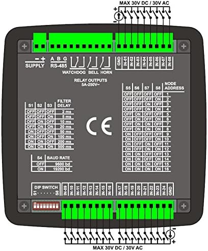
Nọmba 3.2: Pada view of the DKM-0224 showing power supply terminals, RS-485 connections, relay outputs, and 24 digital input terminals (IN-01 to IN-24).
- Ibi ti ina elekitiriki ti nwa: Connect the main power supply to the designated terminals. The unit accepts 19-150VDC or 85-305VAC.
- Digital Inputs (IN-01 to IN-24): Connect your alarm sources to these 24 optically isolated inputs. Each input can handle up to 30V DC/AC.
- Awọn igbejade Isọjade: Connect external devices like horns or bells to the "WATCHDOG", "BELL", and "HORN" relay output terminals. These are rated 5A/250V.
- RS-485: For Modbus RTU communication, connect the RS-485 A, B, and G terminals to your communication network.
3.3 DIP Yipada Eto
The DKM-0224 features DIP switches on the back panel for configuring input filter delay and RS-485 baud rate.
- Filter Delay (S1-S3): Adjust the input detection delay from 2ms to 500ms to prevent false alarms from transient signals. Refer to the back panel diagram for specific switch combinations.
- Baud Rate (S4): Set the RS-485 communication baud rate to either 9600 bd or 19200 bd to match your system.
- Node Address (S5-S8): Configure the Modbus node address using DIP switches S5-S8.
4. Isẹ
The DKM-0224 provides clear visual and audible indications for alarm conditions. Understanding the LED states and pushbutton functions is crucial for proper operation.

Nọmba 4.1: Detailed operational guide for the DKM-0224, explaining LED behaviors, audible warnings, relay functions, and pushbutton controls.
4.1 Alarm LEDs
- FAST FLASH (Red): Indicates the first detection of a fault.
- SLOW FLASH (Red): Activated when the ACK (acknowledge) pushbutton is pressed and the fault signal is still active.
- STEADY ON (Red): Activated if the fault signal disappears at SLOW FLASH condition.
- LED PA: The alarm LED turns off when the RESET pushbutton is pressed and the fault signal is not present.
4.2 Audible Warnings
- When a fault signal is detected, the internal buzzer turns on with a period of 1 second. If the ACK pushbutton is pressed, the buzzer turns off. If ACK is not pressed within 1 minute, it switches to slow sound mode (beeps once every 10 seconds).
4.3 Awọn abajade yiyi pada
- HORN RELAY: If any "red" alarm LED turns on, then the horn relay also turns on. The relay turns off when the HORN pushbutton is pressed.
- BELL RELAY: If any "green" alarm LED turns on, then the bell relay also turns on. The relay turns off when the ACK pushbutton is pressed.
- WATCHDOG RELAY: A watchdog relay turns on. If the board fails, then the watchdog relay turns off.
4.4 Other LEDs
- HORN/BELL LED: The HORN relay turns on if the red LEDs are active. If the HORN relay is not on and the BELL relay is on, then the green LEDs are active. Both are off when no alarms are active.
- SAFE/FAIL LED: If an internal fault condition is detected in the unit, this LED will turn on "red", otherwise it turns on "green".
4.5 Pushbutton Functions
- ACK (Acknowledge): When ACK is pressed, fast flashing LEDs switch to slow flash (or steady on) mode, and the internal buzzer turns off.
- Tun: When RESET is pressed, all alarm LEDs turn off and both relay bells turn off. If a fault signal is present, the alarm will occur again.
- Idanwo: When pressed, all LEDs will turn on and green, alternatively and the buzzer sounds.
- Iwo: When pressed, HORN and BELL relays will turn on alternatively for 1 second.
5. Itọju
The Datakom DKM-0224 is designed for reliable operation with minimal maintenance. Regular checks can help ensure its longevity and proper function.
- Ninu: Keep the front panel clean and free of dust. Use a soft, dry cloth for cleaning. Avoid abrasive cleaners or solvents.
- Awọn ayẹwo Asopọmọra: Ṣe àyẹ̀wò gbogbo àwọn ìsopọ̀ wáyà láti rí i dájú pé wọ́n wà ní ààbò àti pé wọn kò ní ìbàjẹ́.
- Awọn ipo Ayika: Rí i dájú pé àyíká iṣẹ́ náà wà láàrín ìwọ̀n otutu àti ọriniinitutu tí a sọ tẹ́lẹ̀ láti dènà ìbàjẹ́.
6. Laasigbotitusita
If the DKM-0224 is not functioning as expected, consider the following common issues:
- Ko si Agbara:
- Verify the power supply connections are correct and secure.
- Ensure the power source is providing the correct voltage (19-150VDC or 85-305VAC).
- Itaniji ko ṣiṣẹ:
- Check the input wiring for the specific channel.
- Ensure the alarm source is active and providing the correct signal to the input.
- Verify DIP switch settings for filter delay are not excessively long, potentially delaying alarm detection.
- Audible Alarm Not Sounding:
- Check if the internal buzzer is enabled (if configurable).
- Ensure the ACK button has not been pressed, silencing the buzzer.
- Ìjáde Relay Kò Ṣiṣẹ́:
- Verify the relay output wiring is correct.
- Ensure the associated alarm condition is active and the relay logic is met (e.g., red LED for Horn relay).
- Check the WATCHDOG relay for internal fault indications (SAFE/FAIL LED).
- Communication Issues (RS-485):
- Check RS-485 wiring (A, B, G).
- Verify DIP switch settings for baud rate and node address match the communication system.
- Ensure proper termination resistors are used on the RS-485 bus if applicable.
7. Imọ ni pato
The following table details the technical specifications of the Datakom DKM-0224 Alarm Annunciator.
Nọmba 7.1: Pariview of technical specifications, back view wiring, and panel cut-out dimensions for the DKM-0224.
| Paramita | Iye |
|---|---|
| Igbewọle Ipese | 19-150VDC (optional 88-400VDC, 85-270VAC) |
| Agbara agbara | <4 VA |
| Fault Inputs | 24 opto-isolated inputs, with positive inputs and common negative terminals, protected against high voltage and electrical noise. |
| Input Impedance | 40k-ohms (opt. 130k-ohms) |
| Ti nwọle lọwọlọwọ | O pọju. 30mA @ 1VDC |
| Aabo Idaabobo | 1000V / 50us |
| Ìyàraẹniṣọ́tọ̀ | 1000V AC, 1 iseju |
| Filter Delay | 2-5-10-20-50-100-200-500ms selectable |
| Visual Warnings | 26 ultra-bright and bicolor LEDs (red-green) |
| Ikilo Ngbohun | Internal 23mm buzzer, 80dB |
| Awọn ọnajade Relay | 3 outputs, 5A @ 250V AC |
| Serial Port | RS-485 |
| Iru ifihan agbara | RS-485 |
| Ilana | Modbus RTU |
| Oṣuwọn Baud | 9600 / 19200 baud |
| Ìyàraẹniṣọ́tọ̀ | 1000V AC, 1 iseju |
| Iwọn otutu nṣiṣẹ. Ibiti o | -20°C ... +70°C |
| Ibi ipamọ otutu. Ibiti o | -40°C ... +85°C |
| O pọju. Ọriniinitutu ibatan | %95 non-condensing. |
| Idaabobo ìyí | IP 65 (Front, with gasket), IP 30 (Rear panel) |
| Apade | Flame retardant ROHS compliant, high temperature ABS/PC (UL94 V0) |
| Fifi sori ẹrọ | Flush mount with rear retaining plastic brackets. |
| Awọn asopọ | Two part connection system. |
| USB Abala | o pọju. 2.5mm² |
| Awọn iwọn | 164x164x60mm (WxHxD) |
| Panel Ge-jade | 140x140mm |
| Iwọn | 400 gr |
| Awọn itọsọna EU | 2006/95/EC (LVD), 2004/108/EC (EMC) |
| Awọn ajohunše itọkasi | EN 61010 (safety), EN 61326 (EMC) |
8. Atilẹyin ọja ati Support
Information regarding the product warranty and technical support is typically provided by the manufacturer, Datakom, or your authorized reseller at the time of purchase. Please refer to your purchase documentation or contact Datakom directly for details on warranty coverage, service, and technical assistance.
For further information, you may visit the official Datakom webaaye tabi kan si atilẹyin alabara wọn.