
1. Ifihan
This manual provides essential information for the safe and effective installation, operation, and maintenance of the Schneider Electric TeSys D Contactor, model LC1D25G7. This device is a 3-pole contactor designed for AC-3 applications, rated for 25 Amperes at 440 Volts, and features a 120 Volts AC coil. Please read this manual thoroughly before proceeding with any work involving the contactor.
2. Alaye Aabo
WARNING: Risk of Electric Shock or Arc Flash
- Àwọn òṣìṣẹ́ tó ní ìmọ̀ nìkan ló gbọ́dọ̀ ṣe iṣẹ́ ìfisílé, àtúnṣe, àtúnṣe àti ìtọ́jú.
- Always disconnect power before working on the contactor or associated equipment.
- Lo ohun elo aabo ti ara ẹni ti o yẹ (PPE) ati tẹle awọn iṣe iṣẹ itanna ailewu.
- Rí i dájú pé gbogbo wáyà wa ní ìbámu pẹ̀lú àwọn òfin iná mànàmáná ti agbègbè àti ti orílẹ̀-èdè.
- Má ṣe lo ohun èlò ìfọwọ́sowọ́pọ̀ náà bí ó bá bàjẹ́ tàbí tí ó bá dàbí pé kò ṣiṣẹ́ dáadáa.
3. Ọja Ipariview
The Schneider Electric TeSys D Contactor LC1D25G7 is a robust electromechanical switch used for controlling electric motors, heating, lighting, and other electrical loads. It features three main power poles and auxiliary contacts for control circuit integration.

Nọmba 3.1: Iwaju view of the Schneider Electric TeSys D Contactor LC1D25G7, showing the main power terminals (L1, L2, L3, T1, T2, T3) and control coil terminals (A1, A2), along with auxiliary contacts (NO, NC).

Nọmba 3.2: Apa view of the contactor, displaying the product label with technical specifications, certifications (EAC, CE), and manufacturing details.

Nọmba 3.3: Isalẹ view of the contactor, showing the mounting points and the lower power terminals (2T1, 4T2, 6T3).

Nọmba 3.4: Oke view of the contactor, illustrating the upper power terminals (1L1, 3L2, 5L3) and the general construction.
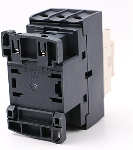
Nọmba 3.5: Apa miran view of the contactor, highlighting the DIN rail mounting mechanism and additional structural details.

Nọmba 3.6: The product packaging for the Schneider Electric TeSys D Contactor LC1D25G7, showing branding and key product identifiers.
4. Eto ati fifi sori
Proper installation is crucial for the safe and reliable operation of the contactor. Refer to the wiring diagrams provided with your specific application or system documentation.
4.1 Iṣagbesori
- The contactor can be mounted on a 35mm DIN rail or directly to a panel using screws.
- Ensure adequate ventilation around the contactor to prevent overheating.
- Mount the contactor vertically on a flat, stable surface.
4.2 Onirin
- Connect the main power circuit to terminals 1L1, 3L2, 5L3 (input) and 2T1, 4T2, 6T3 (output).
- Connect the control circuit (120V AC) to the coil terminals A1 and A2.
- Utilize auxiliary contacts (e.g., 13 NO, 21 NC) for control logic as required by your application.
- Ensure all wire connections are tight and secure to prevent loose connections and potential arcing.
- Use appropriate wire gauges for the current ratings.
5. Awọn ilana Iṣiṣẹ
The TeSys D Contactor operates by energizing its coil, which creates an electromagnetic field that pulls the armature, closing the main power contacts. When the coil is de-energized, a spring returns the armature to its original position, opening the main contacts.
- Gbigbe okun: Apply 120V AC to terminals A1 and A2. The contactor will audibly click as the main contacts close.
- Mimu okun kuro: Remove the 120V AC supply from terminals A1 and A2. The contactor will release, and the main contacts will open.
- Itọkasi ipo: Some models may include a visual indicator to show the contactor's state (open/closed).
6. Itọju
Regular inspection and maintenance can extend the lifespan of the contactor and ensure reliable operation.
- Ayewo wiwo: Periodically check for signs of wear, damage, discoloration, or loose connections.
- Ninu: Keep the contactor free from dust, dirt, and debris. Use a dry, non-conductive cloth or compressed air. Do not use solvents.
- Àyẹ̀wò Olùbáṣepọ̀: For critical applications, periodically inspect the main contacts for pitting or excessive wear. Replace the contactor if contacts are severely worn.
- Ṣayẹwo wiwọ: Re-tighten all terminal screws to the specified torque values (refer to product label or Schneider Electric documentation) during routine maintenance.
7. Laasigbotitusita
Yi apakan adirẹsi wọpọ oran ti o le dide nigba awọn isẹ ti awọn contactor.
- Contactor Does Not Energize:
- Check if 120V AC is present at coil terminals A1 and A2.
- Verify control circuit wiring for breaks or loose connections.
- Inspect the coil for damage (e.g., burnt smell, visible charring).
- Àwọn ohùn olùbáṣepọ̀ tó pọ̀ jù:
- Ensure the mounting screws are tight.
- Check for foreign objects obstructing the armature movement.
- Verify the coil voltage jẹ laarin awọn pato.
- Olubasọrọ Overheats:
- Check for excessive load current exceeding the contactor's rating.
- Ensure proper ventilation and ambient temperature are within limits.
- Inspect main contacts for signs of pitting or high resistance.
- Main Contacts Fail to Close/Open Reliably:
- Inspect contacts for wear, welding, or foreign material.
- Ṣe àyẹ̀wò ìpele coiltage and ensure it is stable.
- Check for mechanical obstructions.
8. Awọn pato
| Sipesifikesonu | Iye |
|---|---|
| Olupese | Schneider |
| Nọmba apakan | LC1D25G7 |
| Nọmba Awoṣe Nkan | LC1D25G7 |
| Iwọn Nkan | 13 iwon |
| Package Mefa | 4.45 x 3.66 x 2.05 inches |
| Ohun elo | Ṣiṣu |
| Voltage (Coil) | 120 folti AC |
| Amperage Capacity (AC-3) | 25 Amps |
| Awọn ọpá | 3P (3 NO) |
| Ti won won operational Voltage (Ue) | Up to 690 V AC |
| Ti won won idabobo Voltage (Ui) | 600 V (UL/CSA), 690 V (IEC) |
| Ti won won Impulse withstand Voltage (Uimp) | 6 kV |
9. Atilẹyin ọja ati Support
Schneider Electric products are designed and manufactured to high-quality standards. For information regarding warranty terms, technical support, or service, please refer to the official Schneider Electric webojula tabi kan si wọn onibara iṣẹ taara.
O le wa alaye diẹ sii ati awọn orisun atilẹyin lori awọn Oṣiṣẹ Schneider Electric webojula.