1. Ifihan
This manual provides detailed instructions for the installation, operation, and maintenance of the Novastar MCTRL300 Synchronous LED Sender Box. Please read this manual thoroughly before using the device to ensure proper functionality and to prevent damage.
The Novastar MCTRL300 is a high-performance LED display controller designed for full-color LED screens, offering reliable and stable operation for various indoor and outdoor applications.
2. Ọja Ipariview ati Awọn ẹya ara ẹrọ
The Novastar MCTRL300 is a full-color sending card and LED display accessory. It is engineered to manage LED displays with high efficiency and precision.
Awọn ẹya pataki:
- Igbewọle DVI: One (1) DVI input for video signal connection.
- Iṣawọle Olohun: Supports external audio input.
- Abajade data: Two (2) RJ45 ports for data output, supporting hot backup functionality for enhanced reliability.
- Atokun Iṣakoso: USB control interface, allowing for cascading multiple units.
- Agbara Pixel: Supports up to 1.3 million pixels.
- Awọn ipinnu atilẹyin: Includes 1280×1024, 1024×1200, 1600×848, 1920×712, 2048×668, and custom resolutions.
- Light Sensor Interface: One (1) interface for automatic brightness adjustment based on ambient light conditions.
- Ohun elo: Suitable for both indoor and outdoor full-color RGB LED display control.
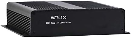
olusin 2.1: Iwaju view of the Novastar MCTRL300 LED Sender Box, showing the model name.
3. Eto ati awọn isopọ
This section details the physical connections required to set up your Novastar MCTRL300 LED Sender Box.
3.1 Ru Panel Pariview

Figure 3.1: Rear panel of the MCTRL300, illustrating power input, DVI, USB, audio, UART, and RJ45 data output ports.
- Power Input (AC 100-240V ~ 50/60Hz): Connect the provided power cable to this port and to a suitable power outlet. The power switch is located next to this port.
- Igbewọle DVI: Connect your video source (e.g., PC graphics card) to this port using a DVI cable.
- Ibudo USB: Connect a USB cable from your control PC to this port for device configuration and control.
- Iṣawọle Olohun: Connect an external audio source if audio transmission is required.
- RJ45 Data Output (OUT1, OUT2): Connect standard Ethernet cables from these ports to the receiving cards of your LED display. OUT1 and OUT2 support hot backup.
- UART IN/OUT: Used for cascading multiple sender boxes or for specific control scenarios.
- Sensọ Imọlẹ: Connect an external light sensor for automatic brightness adjustment.
3.2 Asopọ aworan atọka
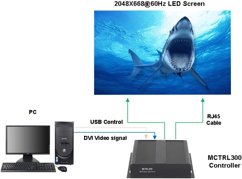
Figure 3.2: Typical connection setup for the MCTRL300, illustrating DVI video signal, USB control, and RJ45 data output to an LED screen.
- Connect the DVI output from your PC's graphics card to the DVI input port on the MCTRL300.
- Connect a USB cable from your PC to the USB port on the MCTRL300. This enables software control and configuration.
- Connect one or more RJ45 Ethernet cables from the MCTRL300's OUT1/OUT2 ports to the input ports of the first receiving card in your LED display panel chain. Ensure proper cabling for the entire LED screen.
- Connect the power cable to the MCTRL300 and a power source.
- Turn on the power switch on the rear panel of the MCTRL300. The "RUN" and "STATUS" indicators will illuminate.
4. Awọn ilana Iṣiṣẹ
After completing the physical connections, the MCTRL300 is ready for operation. Configuration and content management are typically performed using dedicated software on the connected PC.
- Agbara Tan: Ensure all connections are secure, then switch on the power to the MCTRL300 using the rear panel switch.
- Iṣeto ni Sọfitiwia: Use the Novastar control software on your PC to detect the MCTRL300. Configure the LED display parameters, including resolution, screen mapping, and brightness settings. Refer to the software's user guide for detailed instructions.
- Sisisẹsẹhin akoonu: Once configured, the MCTRL300 will transmit the video signal from your PC to the LED display. Ensure your PC's display settings match the configured resolution for optimal output.
- Atunse Imọlẹ: If a light sensor is connected, the display brightness can be automatically adjusted. Manual adjustment is also possible via the control software.
5. Itọju
Proper maintenance ensures the longevity and reliable performance of your MCTRL300 LED Sender Box.
- Ninu: Regularly clean the exterior of the device with a soft, dry cloth. Avoid using liquid cleaners or solvents. Ensure ventilation openings are free from dust and debris.
- Awọn ipo Ayika: Operate the device within its specified temperature and humidity ranges. Avoid exposure to extreme temperatures, direct sunlight, or high moisture environments.
- Iṣakoso USB: Ensure all cables are securely connected and not under strain. Periodically check for any signs of wear or damage to cables.
- Awọn imudojuiwọn sọfitiwia: Keep the Novastar control software and device firmware updated to the latest versions for optimal performance and compatibility.
6. Laasigbotitusita
This section provides solutions to common issues you might encounter with the MCTRL300.
| Isoro | Owun to le Fa | Ojutu |
|---|---|---|
| No display on LED screen. |
|
|
| "RUN" or "STATUS" indicator not lit. |
|
|
| Display shows abnormal colors or flickering. |
|
|
If the problem persists after attempting these solutions, please contact Novastar technical support.
7. Awọn pato
Technical specifications for the Novastar MCTRL300 LED Sender Box.
| Ẹya ara ẹrọ | Ẹ̀kúnrẹ́rẹ́ |
|---|---|
| Brand | Novastar |
| Awoṣe | MCTRL300 |
| Atọka Input | 1 x DVI, External Audio |
| O wu Interface | 2 x RJ45 (Data Output, Hot Backup), UART OUT |
| Iṣakoso Interface | 1 x USB, UART IN |
| Pixel Capacity | Awọn piksẹli Milili 1.3 |
| Awọn ipinnu atilẹyin | 1280×1024, 1024×1200, 1600×848, 1920×712, 2048×668, or custom |
| Pataki Awọn ẹya ara ẹrọ | Light Sensor Interface for auto brightness adjustment, Cascading support via USB |
| Ibi ti ina elekitiriki ti nwa | AC 100-240V ~ 50 / 60Hz |
| Iwọn Nkan | 3.88 poun (isunmọ 1.76 kg) |
| Package Mefa | 11.1 x 8.54 x 4.57 inches (iwọn 28.2 x 21.7 x 11.6 cm) |

Figure 7.1: MCTRL300 package contents, including the sender box and necessary cables.
8. Atilẹyin
For further assistance, technical support, or warranty inquiries, please refer to the official Novastar webaaye tabi kan si alagbata ti a fun ni aṣẹ.
Always ensure you have your product model number (MCTRL300) and purchase details available when contacting support.