
ANMBEST AMS1117-3.3
ANMBEST AMS1117-3.3 DC-DC Voltage Regulator Module Instruction Manual
1. Ifihan
This instruction manual provides essential information for the safe and effective use of the ANMBEST AMS1117-3.3 DC-DC Voltage Regulator Step Down Power Supply Buck Module. This module is designed to convert an input voltage range of 4.75V-12V DC into a stable 3.3V DC output, with a maximum output current of 800mA. It is suitable for various electronic projects requiring a regulated 3.3V power supply.
2. Awọn ẹya ara ẹrọ
- Rere Voltage Regulator Step Down Power Supply Module.
- Supports DC 4.75V-12V input.
- Provides fixed 3.3V DC output.
- Maximum output current: 800mA.
- Simple dual-panel design with 2-pin single row pins for easy input/output connection.
- Integrated overheat shutdown circuit for overload and over-temperature protection.
3. Awọn pato
| Paramita | Iye |
|---|---|
| Iṣagbewọle Voltage | DC 4.75V - 12V |
| O wujade Voltage | 3.3V (Ti o wa titi) |
| Ijade lọwọlọwọ | 800MA (Max) |
| Line Adjustment Rate | 0.2% (O pọju) |
| fifuye Regulation | 0.4% (O pọju) |
| Ibiti o gbona Junction Nṣiṣẹ | -40 si 125 °C |
| Ibi ipamọ otutu | -65 si 150 °C |
| Voltage Iyatọ | 1.3V (O pọju) |
| Ipin lọwọlọwọ | 900 ~ 1500mA |
| Quiescent Lọwọlọwọ | 10MA (Max) |
| Ripple Suppression | 60dB (Min) |
| Module Iwon | 8.6mm x 12.33mm |
4. Awọn iṣọra aabo
- Do not exceed the specified operating voltage (4.75V-12V DC input), as this can damage the module.
- Exceeding the maximum allowable power consumption will result in excessive chip temperature, potentially leading to damage or reduced lifespan.
- Ensure correct polarity when connecting the input power. Reversing polarity will result in a short circuit and damage the module.
- Handle the module with care to avoid electrostatic discharge (ESD) damage.
5. Eto ati Asopọ
The AMS1117-3.3 module features three main pins for connection: VIN (Input Voltage), GND (Ground), and OUT (Output Voltage). Refer to the connection diagram below for proper wiring.

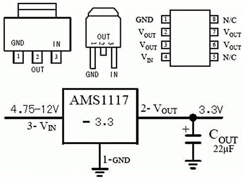
- Input Connection (VIN): Connect the positive terminal of your DC power source (4.75V-12V) to the 'VIN' pin on the module.
- Isopọ ilẹ (GND): Connect the negative terminal of your DC power source to the 'GND' pin. Ensure this is a common ground for both input and output.
- Output Connection (OUT): The regulated 3.3V DC output will be available between the 'OUT' pin (positive) and the 'GND' pin (negative). Connect your 3.3V load to these pins.
- Ìmúdájú: Before connecting sensitive components, it is recommended to verify the output voltage using a multimeter to ensure it is stable at 3.3V.
Visual Guide: USB Power to 3V Down Converter
This video demonstrates a practical application of a similar buck converter, showing how to convert USB power to a lower voltage, which can be adapted for the AMS1117-3.3 module to provide 3.3V.
6. Awọn ilana Iṣiṣẹ
Once properly connected, the AMS1117-3.3 module will automatically regulate the input voltage to a stable 3.3V output. No further adjustments are required as this is a fixed voltage regulator. Ensure your load does not draw more than 800mA to maintain stable operation and prevent overheating.
Visual Guide: AMS1117 LDO Buck Module Overview
Yi fidio pese ohun loriview of the AMS1117 LDO buck module, demonstrating its functionality and how it can be used in various electronic setups. It covers both fixed and adjustable output versions, offering valuable context for understanding the 3.3V fixed output module.
7. Awọn ohun elo
The AMS1117-3.3 module is versatile and can be used in various electronic projects, including:
- SCM (Single-Chip Microcomputer) project designs requiring a 3.3V power supply.
- Powering 3.3V low power consumption microcontrollers (MCUs).
- FPGA/CPLD PLD Programmable Logic Systems.
- ARM7, ARM9, ARM11, STM32 development boards.
- High-efficiency linear regulator applications.
- Active power regulator and battery charger circuits.
8. Laasigbotitusita
- Ko si Ijade Voltage: Ṣayẹwo igbewọle voltage (VIN) to ensure it is within the 4.75V-12V range. Verify all connections for proper contact and polarity.
- Ìwọ̀n Ìgbéjáde Tí Kò Tọ́tage: Ensure the module is correctly wired. If the output is significantly off, the module may be damaged.
- Igbóná púpọ̀: Reduce the load current to ensure it does not exceed 800mA. Verify that the input voltage is not excessively high, which can increase power dissipation. Ensure adequate ventilation around the module.
- Ibajẹ modulu: If the module shows signs of physical damage, burning, or does not function after verifying connections and power, it may be faulty and require replacement.
9. Itọju
The AMS1117-3.3 voltage regulator module requires minimal maintenance. To ensure optimal performance and longevity:
- Jeki module naa mọ ki o si ni ominira lati eruku, ọrinrin, ati awọn nkan ti o bajẹ.
- Avoid physical stress or impact that could damage the components or solder joints.
- Ensure proper heat dissipation, especially when operating at higher input voltages or near the maximum current limit.
10. Atilẹyin ọja ati Support
For warranty information, technical support, or any inquiries regarding your ANMBEST AMS1117-3.3 Voltage Regulator Module, please refer to the product packaging or contact ANMBEST customer service directly through their official channels. Keep your purchase receipt for warranty claims.
Ask a question about this manual
Ask about setup, troubleshooting, compatibility, parts, safety, or missing instructions. Manuals+ will review the question and use this page’s manual context to help answer it.