
Insize 9501-1200
Insize Coating Thickness Gauge 9501-1200
Itọsọna olumulo
1. Ọja Ipariview
The Insize Coating Thickness Gauge 9501-1200 is a precision instrument designed for non-destructive measurement of coating thickness. It is capable of measuring both non-magnetic coatings on magnetic substrates (ferrous, Fe) and non-conductive coatings on non-magnetic substrates (non-ferrous, NFe). This gauge is widely used in manufacturing, quality control, and inspection processes to ensure proper coating application.
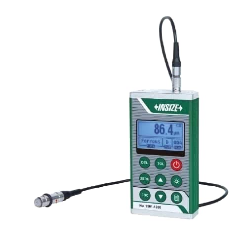
Figure 1: Insize Coating Thickness Gauge 9501-1200. The image shows the compact, handheld device with a digital display, control buttons, and a connected measurement probe.
2. Alaye Aabo
- Always handle the gauge and probes with care to prevent damage.
- Ma ṣe fi ẹrọ naa han si awọn iwọn otutu to gaju, ọriniinitutu, tabi agbegbe ibajẹ.
- Avoid dropping the instrument or subjecting it to strong impacts.
- Keep the device away from strong magnetic fields, which can affect measurement accuracy.
- Rí i dájú pé a fi àwọn bátìrì sí i dáadáa, kí o sì da àwọn bátìrì tí a ti lò nù ní ọ̀nà tó tọ́.
- Má ṣe gbìyànjú láti tú tàbí tún ẹ̀rọ náà ṣe fúnra rẹ. Tọ́ka sí àwọn òṣìṣẹ́ iṣẹ́ tó péye.
3. Product Components and Standard Delivery
The Insize Coating Thickness Gauge 9501-1200 comes with the following standard components:
- Main unit (1 pc)
- Magnetic induction probe (Fe) (1 pc)
- Eddy current probe (NFe) (1 pc)
- Zero calibration block for Fe (1 pc)
- Calibration foils (50μm, 100μm, 250μm, 500μm, 1000μm) (1 set)
- 1.5V AA battery (2 pcs)
- USB cable and software (1 set)
Optional accessories are also available for specialized applications, such as different types of probes for specific measurement needs.
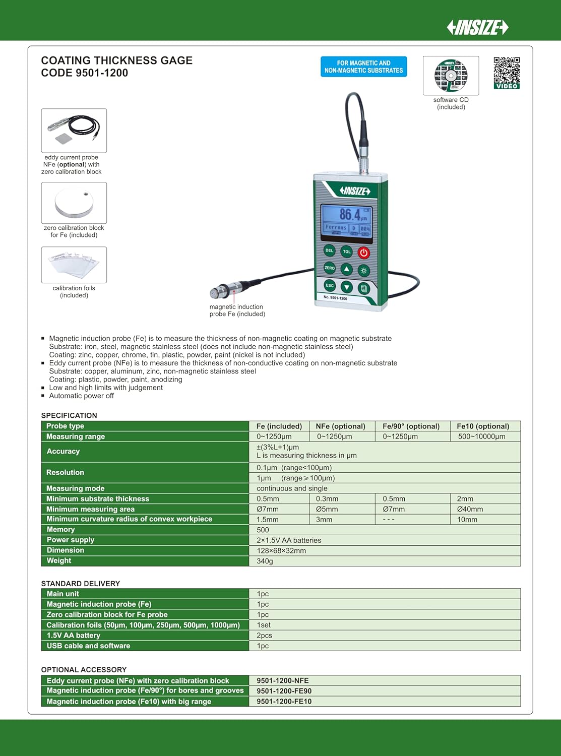
Figure 2: Diagram showing the main unit, various probes (magnetic induction and eddy current), zero calibration block, and calibration foils. This image also details the standard delivery items and optional accessories.
4. Eto
4.1 Fifi sori batiri
- Locate the battery compartment on the back of the gauge.
- Ṣii ideri batiri naa.
- Fi awọn batiri 1.5V AA meji sii, ni idaniloju polarity ti o pe (+/-).
- Pa ideri batiri naa ni aabo.
4.2 Iwadi Asopọ
Connect the desired measurement probe (Fe or NFe) to the probe port on the top of the main unit. Ensure the connector is firmly seated.
4.3 Agbara Tan / Pa
Tẹ awọn Agbara button (red button) to turn the gauge on. Press and hold the Agbara bọtini lẹẹkansi lati pa a.
4.4 Initial Calibration (Zero Calibration)
Before first use or after changing probes, perform a zero calibration:
- Ensure the probe is clean.
- Place the probe firmly and flatly on the corresponding zero calibration block (e.g., Fe probe on Fe zero block).
- Tẹ awọn ZERO button. The display should show "0.0" or a value very close to zero.
- Repeat for the NFe probe and its respective zero block if applicable.
4.5 Calibration with Foils
For accurate measurements, especially when measuring different materials or ranges, calibrate using the provided calibration foils:
- Place a calibration foil (e.g., 100μm) on the zero calibration block.
- Place the probe firmly on the foil.
- Adjust the reading to match the foil's thickness using the up/down arrow buttons.
- Repeat with other foils as needed to cover the expected measurement range.
5. Awọn ilana Iṣiṣẹ
5.1 Ipilẹ wiwọn
- Ensure the gauge is powered on and calibrated.
- Select the appropriate probe (Fe for magnetic substrates, NFe for non-magnetic substrates). The gauge typically auto-detects the substrate type.
- Place the probe gently and perpendicularly onto the coated surface to be measured.
- The measurement reading will appear on the display. Hold the probe steady until the reading stabilizes.
- Lift the probe from the surface to take another measurement.
5.2 Awọn ọna wiwọn
The gauge supports different measurement modes:
- Ipo Wiwọn Nikan: Takes one reading each time the probe is applied.
- Continuous Measurement Mode: Allows for continuous readings as the probe is moved across the surface. This is useful for scanning larger areas. Refer to the specific button on your device (often indicated by an icon) to switch between modes.
5.3 Data Ibi ati ÌRÁNTÍ
The gauge has internal memory to store measurement data. Use the designated buttons (e.g., MEM or similar icon) to save readings and recall them later. Consult the on-screen icons for navigation.
5.4 Tolerance Setting
The gauge allows setting upper and lower tolerance limits. If a measurement falls outside these limits, the gauge may provide an audible or visual alert. Use the TOL button to access and adjust tolerance settings.
5.5 Imọlẹ ẹhin
Tẹ awọn Imọlẹ button (often with a lightbulb icon) to turn the display backlight on or off for improved visibility in low-light conditions.
6. Itọju
6.1 Ninu
- Fi aṣọ rírọrùn, gbígbẹ, nu ohun èlò pàtàkì náà. Má ṣe lo àwọn ohun èlò ìfọmọ́ tàbí àwọn ohun èlò ìfọ́mọ́.
- Keep the probe tip clean and free of debris. Use a soft cloth or cotton swab. Do not scratch the probe surface.
6.2 Batiri Rirọpo
When the low battery indicator appears on the display, replace the batteries promptly to ensure accurate readings and prevent data loss. Refer to section 4.1 for battery installation instructions.
6.3 Ibi ipamọ
Store the gauge and its accessories in the provided carrying case in a dry, dust-free environment, away from direct sunlight and extreme temperatures.
6.4 Igbohunsafẹfẹ odiwọn
Regular calibration is crucial for maintaining accuracy. It is recommended to perform zero calibration before each use or when changing measurement conditions. Full calibration with foils should be done periodically, or if you suspect inaccurate readings.
7. Laasigbotitusita
| Isoro | Owun to le Fa | Ojutu |
|---|---|---|
| Gauge does not power on. | Awọn batiri ti o ku tabi ti ko tọ ti fi sori ẹrọ. | Rọpo awọn batiri tabi ṣayẹwo polarity. |
| Awọn kika ti ko pe. | Probe tip dirty; improper calibration; incorrect substrate type selected; strong magnetic interference. | Clean probe tip; perform zero and foil calibration; ensure correct probe/mode for substrate; move away from magnetic sources. |
| Display shows "Err" or "OL". | Measurement out of range; probe not properly seated; sensor error. | Ensure measurement is within specified range; re-seat probe; re-calibrate. If error persists, contact support. |
| No response from buttons. | Ẹ̀rọ náà ti dì; batiri tí kò pọ̀. | Turn off and on again; replace batteries. |
8. Awọn pato
| Paramita | Fe (Magnetic) | NFe (Non-Magnetic) |
|---|---|---|
| Iwọn Iwọn | 0-1250μm | 0-1250μm |
| Yiye | ±(3% + 1μm) | |
| Ipinnu | 0.1μm (range < 100μm), 1μm (range ≥ 100μm) | |
| Ipo Idiwọn | Continuous and single | |
| Sisanra sobusitireti to kere julọ | 0.5mm | 0.3mm |
| Agbegbe Idiwọn Kere | Ø7mm | Ø5mm |
| Minimum Curvature Radius of Convex Workpiece | 1.5mm | 3mm |
| Iranti | 500 kika | |
| Ibi ti ina elekitiriki ti nwa | 2 x 1.5V AA batiri | |
| Iwọn | 128×60×32mm | |
| Iwọn | 340g | |
Note: Specifications are subject to change without notice. Refer to the product packaging or manufacturer's webaaye fun alaye lọwọlọwọ julọ.
9. Atilẹyin ọja ati Support
Warranty information for the Insize Coating Thickness Gauge 9501-1200 is typically provided with your purchase documentation or can be found on the official Insize webojula. Jọwọ ṣe idaduro ẹri rira rẹ fun awọn iṣeduro atilẹyin ọja.
For technical support, service, or inquiries regarding optional accessories, please contact your local Insize distributor or visit the official Insize webojula fun alaye olubasọrọ.
Manufacturer: INSIZE
Date First Available: 4 September 2019
Ask a question about this manual
Ask about setup, troubleshooting, compatibility, parts, safety, or missing instructions. Manuals+ will review the question and use this page’s manual context to help answer it.