
HoldPeak HP-890CN
HoldPeak HP-890CN Digital Multimeter User Manual
Model: HP-890CN
1. Ifihan
Thank you for choosing the HoldPeak HP-890CN Digital Multimeter. This device is designed for stable and reliable performance, featuring an anti-drop design and a clear 25mm high LCD display. It is capable of measuring various electrical parameters including DC/AC voltage, diode, resistance, capacitance, frequency, duty cycle, temperature, and hFE, along with a non-contact voltage (NCV) detection function. Please read this manual thoroughly before use to ensure safe and proper operation.
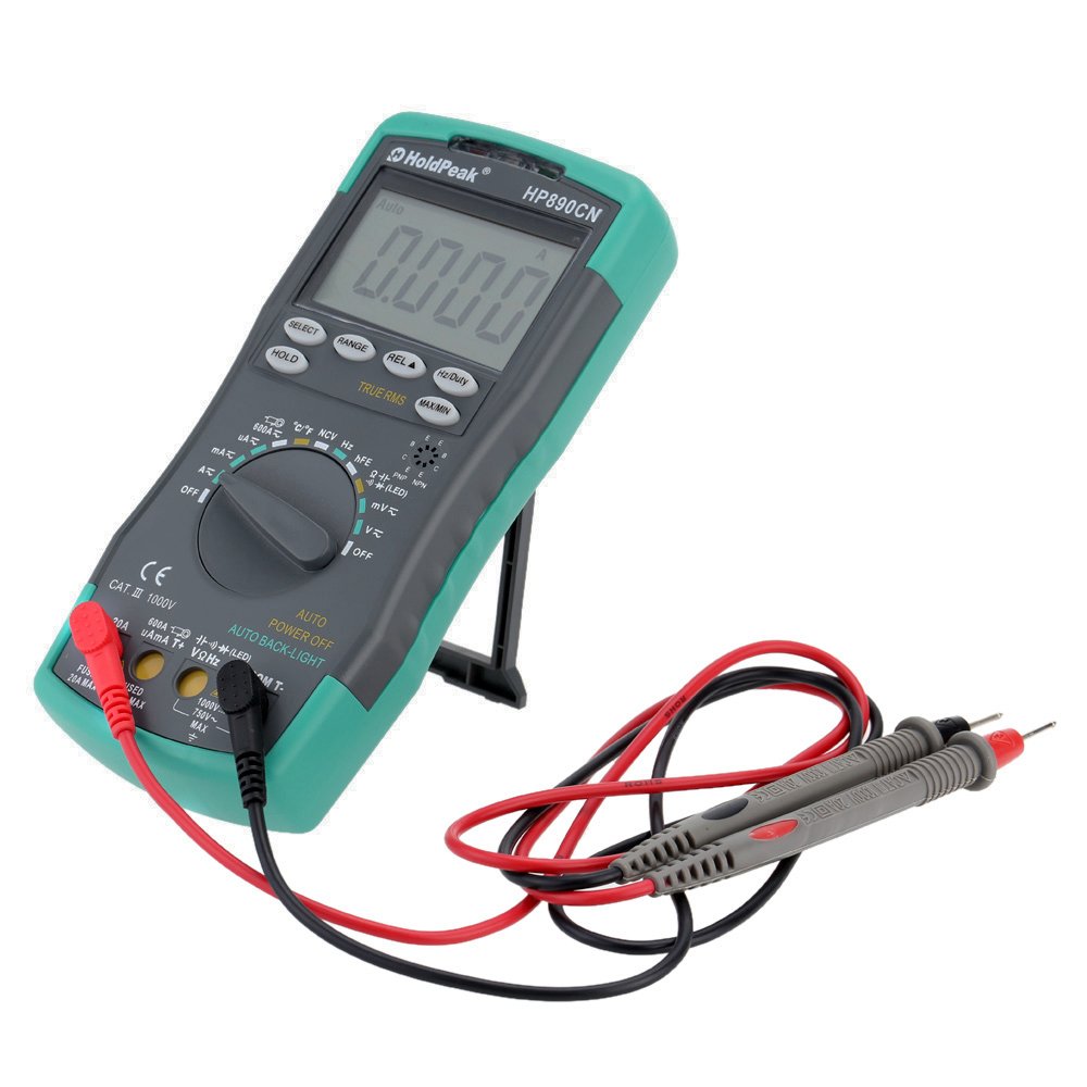
Figure 1: HoldPeak HP-890CN Digital Multimeter
2. Alaye Aabo
WARNING: To avoid electrical shock or damage to the meter, please observe the following safety precautions:
- Always remove test leads from the circuit before opening the case or battery cover.
- Do not operate the meter with the case or battery cover open.
- To prevent damage or injury, ensure quick-acting fuses with the specified amp and volt ratings are installed.
- This device complies with IEC 1010-1 1000V CAT III, Pollution Degree 2 standards.
- Nigbagbogbo lo iṣẹ to pe ati sakani fun awọn wiwọn.
- Maṣe lo voltage tabi lọwọlọwọ ti o kọja awọn opin ti a ti sọ tẹlẹ ti o pọju.
- Ṣọ́ra nígbà tí o bá ń ṣiṣẹ́ pẹ̀lú voltages loke 30V AC RMS, 42V tente oke, tabi 60V DC. Awọn wọnyi ni voltages duro a mọnamọna ewu.
- Pa awọn ika ọwọ mọ lẹhin awọn idena wiwa lakoko awọn wiwọn.

olusin 2: Ẹyìn view of the multimeter showing safety warnings and battery compartment.
3. Ọja Ipariview
The HoldPeak HP-890CN Digital Multimeter features a large LCD display and intuitive controls for ease of use. Below is a diagram illustrating the main components and their functions.

Figure 3: Labeled diagram of the HP-890CN Multimeter.
Awọn eroja pataki:
- Ifihan LCD: Shows measurement readings, units, and function indicators. Features smart backlight.
- Yipada iṣẹ: Rotary switch to select measurement functions (Voltage, Current, Resistance, àti bẹ́ẹ̀ bẹ́ẹ̀ lọ).
- Awọn Jacks ti nwọle:
- COM: Common input jack for the black test lead.
- VΩHz: Iṣagbewọle fun voltage, resistance, frequency, capacitance, diode, and temperature measurements (red test lead).
- mAµA: Input for current measurements up to 600mA (red test lead).
- 20A: Input for current measurements up to 20A (red test lead).
- Awọn bọtini:
- Yan: Toggles between functions within a single rotary switch position (e.g., AC/DC, Diode/Continuity).
- RANGE: Manually selects measurement range (auto-ranging is default).
- REL (Iye ibatan): Measures relative changes.
- Hz/Duty: Selects frequency or duty cycle measurement.
- MU: Dii ti isiyi àpapọ kika.
- TRUE RMS: Indicates True RMS measurement capability for AC.
- O pọju/MIN: Records maximum and minimum readings.
- NCV Induction Area: Fun ti kii-olubasọrọ voltage erin.
- hFE Testing Interface: Socket for transistor testing.
- Ibẹrẹ: Integrated stand for convenient viewing (rotates 180 degrees).
4. Eto
4.1 Fifi sori batiri
The multimeter requires either two 1.5V AAA batteries or one 9V 6F22 battery (not included). The specific battery type included with your product may vary. To install or replace batteries:
- Ensure the multimeter is turned OFF and all test leads are disconnected.
- Wa yara batiri ni ẹhin mita naa.
- Lo screwdriver lati tú dabaru ti o ni aabo ideri batiri naa.
- Yọ ideri batiri kuro.
- Insert the new batteries, observing the correct polarity (+ and -).
- Ropo ideri batiri ki o si Mu dabaru ni aabo.

olusin 4: Ti abẹnu view of the multimeter, showing the battery compartment.
4.2 Nsopọ Awọn itọsọna Igbeyewo
Always connect the black test lead to the COM jack. Connect the red test lead to the appropriate input jack based on the measurement you intend to perform:
- Fun Voltage, Resistance, Capacitance, Frequency, Diode, and Temperature: Connect the red lead to the VΩHz jaki.
- For Current up to 600mA: Connect the red lead to the mAµA jaki.
- For Current up to 20A: Connect the red lead to the 20A jaki.
5. Awọn ilana Iṣiṣẹ
Before taking any measurements, ensure the test leads are correctly connected and the function switch is set to the desired measurement type.
5.1 Agbara Tan / Pa
Rotate the function switch from the OFF position to any desired measurement function to turn the meter ON. Rotate it back to OFF to power it down. The meter features an auto power-off function to conserve battery life.
5.2 Idiwon DC Voltage (V=)
- Set the function switch to the V= position.
- Connect the black test lead to the COM jack and the red test lead to the VΩHz jack.
- Connect the test probes across the component or circuit to be measured, in parallel.
- Ka voltage iye lori ifihan LCD.
5.3 Iwọn AC Voltage (V~)
- Ṣeto iyipada iṣẹ si ipo V ~.
- Connect the black test lead to the COM jack and the red test lead to the VΩHz jack.
- Connect the test probes across the component or circuit to be measured, in parallel.
- Ka voltage value on the LCD display. This meter provides True RMS readings for AC voltage.

Àwòrán 5: Wíwọ̀n ìpele ACtage from a power outlet.
5.4 Measuring DC/AC Current (A= / A~)
CAUTION: Always connect the meter in series with the circuit when measuring current. Ensure the circuit is de-energized before connecting the meter.
- Set the function switch to the A= or A~ position. Use the SELECT button to toggle between DC and AC if necessary.
- So dudu igbeyewo asiwaju si COM Jack.
- Fún ìṣàn omi tó tó 600mA, so okun idanwo pupa náà mọ́ mAµA jack. For currents up to 20A, connect the red test lead to the 20A jaki.
- Break the circuit and connect the test probes in series with the circuit.
- Apply power to the circuit and read the current value on the LCD display.
5.5 Ìwọ̀n Àìdádúró (Ω)
- Ṣeto iyipada iṣẹ si ipo Ω.
- Connect the black test lead to the COM jack and the red test lead to the VΩHz jack.
- Connect the test probes across the component to be measured. Ensure the component is de-energized.
- Ka iye resistance lori ifihan LCD.
5.6 Measuring Capacitance (F)
- Set the function switch to the capacitance (F) position.
- Connect the black test lead to the COM jack and the red test lead to the VΩHz jack.
- Connect the test probes across the capacitor. Ensure the capacitor is fully discharged before measurement.
- Ka iye agbara lori ifihan LCD.
5.7 Measuring Frequency (Hz) / Duty Cycle (%)
- Set the function switch to the Hz/% position.
- Connect the black test lead to the COM jack and the red test lead to the VΩHz jack.
- So awọn iwadii idanwo kọja orisun ifihan.
- Press the Hz/Duty button to toggle between frequency and duty cycle measurements.
- Ka iye lori ifihan LCD.
5.8 Idanwo Diode
- Set the function switch to the Diode/Continuity position. Press SELECT to choose Diode Test.
- Connect the black test lead to the COM jack and the red test lead to the VΩHz jack.
- So ohun elo pupa mọ anode ati ohun elo dudu mọ katode ti diode naa.
- Ka siwaju voltage drop on the LCD display. Reverse the probes to check for open circuit (OL).
5.9 Igbeyewo Ilọsiwaju
- Set the function switch to the Diode/Continuity position. Press SELECT to choose Continuity Test.
- Connect the black test lead to the COM jack and the red test lead to the VΩHz jack.
- So àwọn ìwádìí ìdánwò pọ̀ mọ́ ara wọn ní gbogbo àyíká tàbí ẹ̀yà ara wọn.
- If the resistance is below approximately 50Ω, the buzzer will sound, indicating continuity.
5.10 Ìwọ̀n Ìwọ̀n Ìwọ̀n Ìwọ̀n Ìwọ̀n Ìwọ̀n Ìwọ̀n (°C/°F)
- Ṣeto iyipada iṣẹ si ipo °C/F.
- Connect the K-type thermocouple probe to the VΩHz and COM jacks, observing polarity.
- Fi opin thermocouple si ori tabi nitosi ohun ti a fẹ wọn iwọn otutu rẹ.
- Read the temperature on the LCD display. Use the SELECT button to switch between Celsius and Fahrenheit.
5.11 hFE Test (Transistor Test)
- Ṣeto iyipada iṣẹ si ipo hFE.
- Insert the transistor's Emitter, Base, and Collector leads into the corresponding holes in the hFE socket, ensuring correct NPN or PNP type.
- Read the hFE value (DC current gain) on the LCD display.
5.12 Non-olubasọrọ Voltage (NCV) erin
- Set the function switch to the NCV position.
- Move the NCV induction area of the meter close to the conductor being tested.
- Ti AC voltage is detected (90V to 1000V AC RMS), the NCV red indicator will light up, and the buzzer will sound. The intensity of the sound and light indicates the strength of the detected voltage.
5.13 Awọn iṣẹ pataki
- MU: Tẹ lati di kika lọwọlọwọ lori ifihan naa. Tẹ lẹẹkansi lati tu silẹ.
- REL (Iye ibatan): Press to store the current reading as a reference. Subsequent measurements will show the difference from this reference.
- O pọju/MIN: Press to enter MAX/MIN mode. The meter will display the maximum or minimum reading recorded since entering this mode. Press again to cycle between MAX, MIN, and current reading.
6. Itọju
6.1 Ninu
Pa mita naa pẹlu ipolowoamp cloth and mild detergent. Do not use abrasives or solvents. Keep the contacts of the input jacks clean.
6.2 Batiri Rirọpo
When the battery symbol appears on the LCD, the batteries need to be replaced. Refer to section 4.1 for battery installation instructions.
6.3 Fiusi Rirọpo
WARNING: To avoid electrical shock, disconnect the test leads before opening the case. Replace fuses only with quick-acting fuses of the specified type and rating.
The meter is protected by two fuses:
- F1: 600mA/250V fast-blow fuse for the mAµA input.
- F2: 20A/250V fast-blow fuse for the 20A input.
Lati rọpo fiusi kan:
- Turn the meter OFF and disconnect all test leads.
- Yọ ideri batiri ati awọn batiri kuro.
- Unscrew the screws holding the back case and carefully open the meter.
- Carefully remove the old fuse by gently prying it from its clips.
- Install a new fuse of the correct type and rating.
- Tún so mita náà pọ̀, kí o sì rí i dájú pé gbogbo skru náà ti di mọ́lẹ̀.
7. Laasigbotitusita
- Random values in mV mode: It is normal for the display to show random values in mV mode when the input terminals are open (not connected to a circuit). Simply short the input terminals to zero the reading. This will not affect measurement results.
- Kò sí ìfihàn tàbí ìfihàn tí kò dúdú: Ṣàyẹ̀wò ipele batiri. Rọpo awọn batiri ti o ba kere.
- No reading in current mode: Check if the fuse is blown. Replace if necessary (refer to section 6.3). Ensure test leads are connected to the correct current input jack (mAµA or 20A) and in series with the circuit.
- "OL" tí a fi hàn: Indicates an overload (measurement exceeds the selected range) or an open circuit.
8. Awọn pato
| Paramita | Sipesifikesonu |
|---|---|
| Brand | HoldPeak |
| Awoṣe | HP-890CN |
| Àwọ̀ | Gray + Blue-Green |
| Ohun elo | Ṣiṣu |
| Ifihan to pọju | Awọn iṣiro 6000 |
| Iṣakoso Ibiti | Aifọwọyi Range |
| Iwon iboju | 60 × 35 mm |
| DC Voltage | 60mV/600mV/6V/60V/600V/1000V |
| AC Voltage (RMS otitọ) | 60mV/600mV/6V/60V/600V/750V |
| DC Lọwọlọwọ | 600µA/6000µA/60mA/600mA/6A/20A |
| AC lọwọlọwọ (RMS tootọ) | 600µA/6000µA/60mA/600mA/6A/20A |
| Atako | 600Ω/6KΩ/60KΩ/600KΩ/6MΩ/60MΩ |
| Agbara | 9.999nF/99.99nF/999.9nF/9.999µF/99.99µF/999.9µF/9.99mF/99.99mF |
| Igbohunsafẹfẹ | 9.999Hz/99.99Hz/999.9Hz/9.999KHz/99.99KHz/999.9KHz/9.999MHz |
| Ojuse Cycle | 0.1% si 99.9% |
| Iwọn otutu | -20~1000°C / -4~2222°F |
| Idanwo Diode | Bẹẹni |
| Tẹsiwaju Buzzer | Bẹẹni |
| Transistor hFE Idanwo | 0-1000 |
| Iwari NCV | 90V ~ 1000V AC rms |
| Ibi ti ina elekitiriki ti nwa | 2 * 1.5V AAA batteries / 1 * 9V 6F22 battery (not included) |
| Ayika ti nṣiṣẹ | 0-40°C (32-104°F) |
| Ibi ipamọ Ayika | -20-60 ° C (-4-140 ° F) |
| Ìwọ̀n Ọjà (L×W×H) | Approx. 19 × 8.5 × 3.5 cm (7.67 × 3.35 × 1.37 inches) |
| Iwọn Ọja | 300 giramu (10.58 iwon) |
| Olupese | MIS-E0833 |
| UPC | 783950206936 |
9. Package Awọn akoonu
Package pẹlu awọn nkan wọnyi:
- 1 * HoldPeak HP-890CN Digital Multimeter
- 1 * Apo ipamọ
- 1 * Pair of Test Leads (Red and Black)
- 1 * K-Type Thermocouple Probe
- 1 * Iwe afọwọkọ olumulo Gẹẹsi

Figure 6: Multimeter and included accessories.

Figure 7: Included storage bag for the multimeter.
10. Atilẹyin ọja ati Support
For warranty information or technical support, please refer to the documentation provided with your purchase or contact the seller/manufacturer directly. Keep your purchase receipt as proof of purchase.
Ask a question about this manual
Ask about setup, troubleshooting, compatibility, parts, safety, or missing instructions. Manuals+ will review the question and use this page’s manual context to help answer it.