1. Ifihan
The waveshare FT232RL USB to TTL Adapter Board (Type C) is a communication module designed to convert USB signals to UART (TTL) serial signals. It features the original FT232RL chip, ensuring reliable performance and broad compatibility. This module supports various operating systems including Mac OS, Linux, Android, WinCE, and Windows 7/8/8.1/10/11. It is compatible with both 3.3V and 5V logic levels, making it versatile for different embedded system applications.
This manual provides detailed instructions for setting up, operating, and maintaining your FT232RL USB to TTL Adapter Board.

Figure 1: waveshare FT232RL USB to TTL Adapter Board (Type C)
2. Awọn ẹya ara ẹrọ
The FT232RL USB to TTL Adapter Board incorporates several key features for robust serial communication:
- Original FT232RL Chip: Utilizes the genuine FT232RL integrated circuit for stable and reliable USB to serial conversion.
- Wide OS Compatibility: Supports a broad range of operating systems including Mac OS, Linux, Android, WinCE, and Windows 7/8/8.1/10/11.
- Selectable VCCIO Power Mode: Offers three power output options via a jumper setting:
- VCCIO - 5V: Provides a 5V output.
- VCCIO - 3.3V: Provides a 3.3V output.
- Open Jumper: Allows the module to be powered from the target board (3.3V-5V).
- Awọn itọkasi LED: Equipped with three LED indicators for status monitoring:
- TXD LED: Indicates data transmission.
- RXD LED: Tọkasi gbigba data.
- PWR LED: Ṣe afihan ipo agbara.
- Accessible Pins: Key communication pins (TXD, RXD, RTS#, CTS#) are readily accessible on standard pin headers. Other pins are available on drilled holes, compatible with universal prototype boards for custom applications.
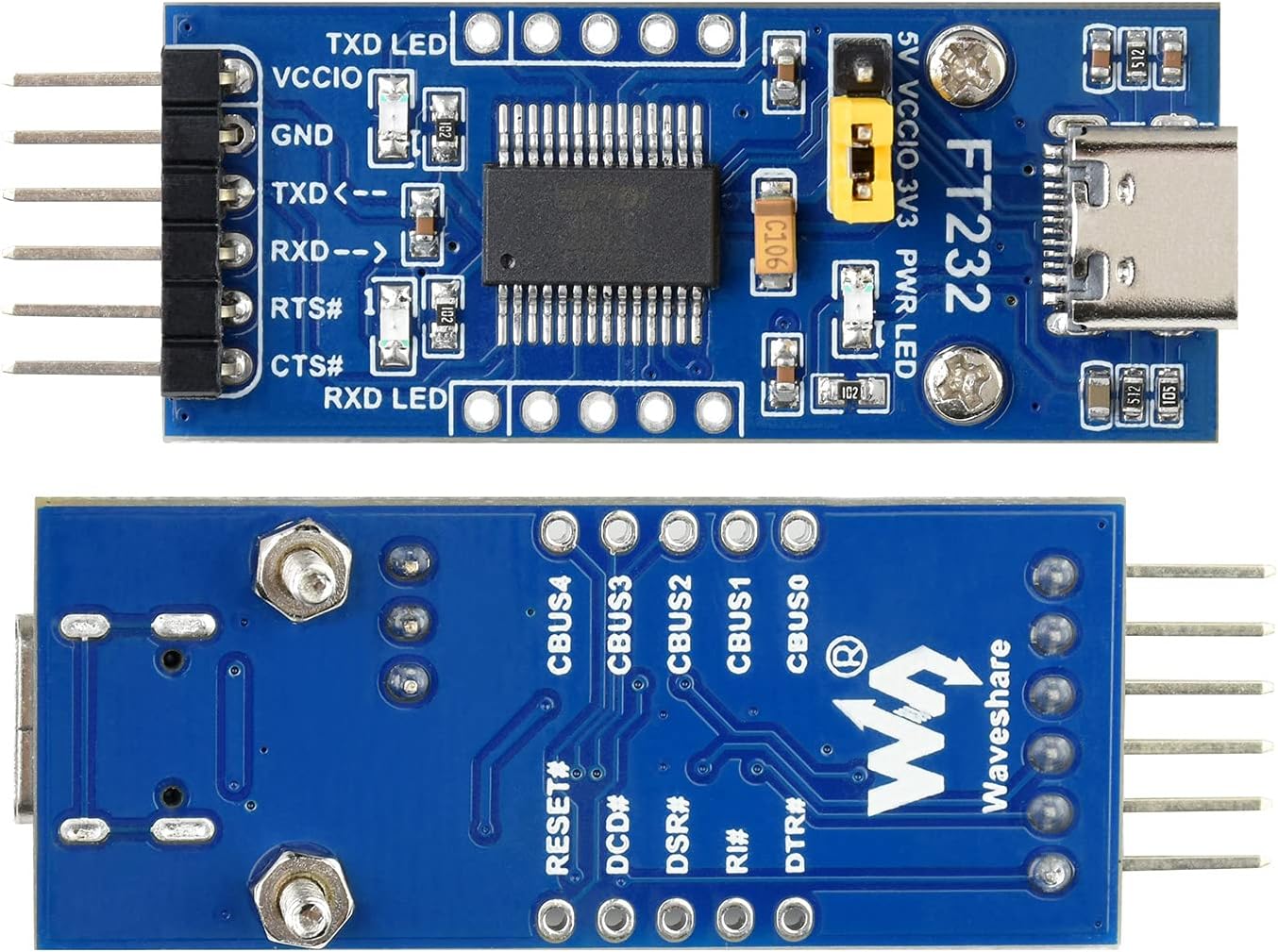
olusin 2: Oke ati Isalẹ View of the Adapter Board
3. Eto
3.1 Driver fifi sori
Before using the FT232RL module, you may need to install the appropriate drivers for your operating system. The FT232RL chip is manufactured by FTDI, and their official website provides the latest drivers. Typically, modern operating systems like Windows 10/11 and Linux distributions may automatically install the necessary drivers upon connection. For older OS versions or specific configurations, manual installation might be required.
- Connect the FT232RL module to your computer's USB port using a USB-C cable.
- If drivers are not automatically installed, visit the FTDI webAaye (www.ftdichip.com/Drivers/VCP.htm) to download the Virtual COM Port (VCP) drivers compatible with your operating system.
- Follow the installation instructions provided by FTDI.
- After successful installation, the device should appear as a COM port in your system's Device Manager (Windows) or `/dev/ttyUSBx` (Linux).
3.2 VCCIO Power Mode Configuration
The module's VCCIO power output can be configured using the onboard jumper. This setting determines the logic level (3.3V or 5V) for the communication pins (TXD, RXD, RTS#, CTS#) and the power supplied to the target board if the jumper is set to 3.3V or 5V output.
- For 5V Logic Level: Place the jumper cap on the pins labeled VCCIO - 5V. This will output 5V on the VCCIO pin and set the logic level to 5V.
- For 3.3V Logic Level: Place the jumper cap on the pins labeled VCCIO - 3.3V. This will output 3.3V on the VCCIO pin and set the logic level to 3.3V.
- Powered by Target Board: Remove the jumper cap entirely. In this configuration, the module's VCCIO pin should be connected to the target board's power supply (3.3V-5V). The module will then adapt its logic level to that of the target board.
CAUTION: Ensure the VCCIO setting matches the logic level of your target device to prevent damage.
4. Awọn ilana Iṣiṣẹ
4.1 Pinout Apejuwe
The module provides standard UART communication pins:
- VCCIO: Power output (3.3V or 5V, depending on jumper setting) or power input from target board.
- GND: Asopọ ilẹ.
- TXD: Transmit Data. Connect to the RXD pin of your target device.
- RXD: Receive Data. Connect to the TXD pin of your target device.
- RTS#: Request To Send (active low).
- CTS#: Clear To Send (active low).
4.2 Hardware Asopọ
To establish serial communication with a microcontroller (MCU) or other serial device, follow these connection guidelines:
- VCCIO ↔ 3.3V or 5V output (if the module is powered from USB and the onboard jumper is shorted to 3.3V or 5V).
- GND ↔ GND.
- TXD ↔ MCU.RX (signal direction: MCU.RX ← FT232 ← PC.TX).
- RXD ↔ MCU.TX (signal direction: MCU.TX ← FT232 ← PC.RX).
- RTS# ↔ MCU.CTS (signal direction: MCU.CTS ← FT232 ← PC.RTS).
- CTS# ↔ MCU.RTS (signal direction: MCU.RTS ← FT232 ← PC.CTS).
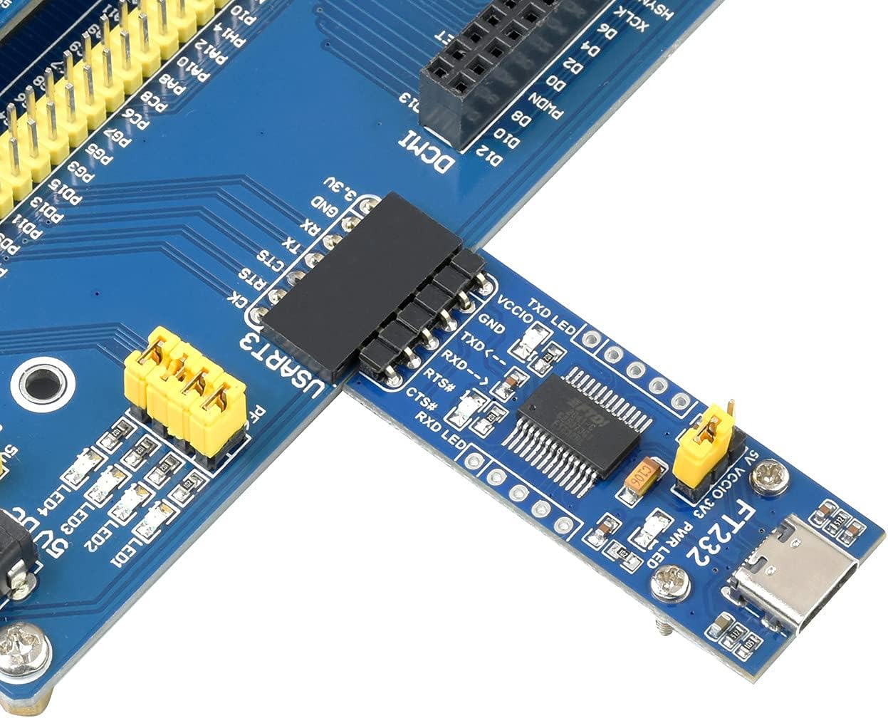
Olusin 3: Example Hardware Connection with an MCU
CAUTION: The module is compatible with TTL level ONLY. To avoid damage, DO NOT directly connect it to RS232 circuits.
4.3 Using with a Terminal Program
Once the drivers are installed and the module is connected to your target device, you can use a serial terminal program (e.g., PuTTY, Tera Term, Arduino Serial Monitor) on your computer to communicate. Configure the terminal program with the correct COM port, baud rate, data bits, parity, and stop bits to match your target device's serial settings.
5. Awọn pato
| Paramita | Iye |
|---|---|
| Nọmba awoṣe | FT232RL |
| Chip | Original FT232RL |
| Iṣagbewọle Voltage | 5V (nipasẹ USB) |
| Ipele Kannaa | 3.3V / 5V (selectable via jumper) |
| Asopọmọra Iru | USB Iru C |
| OS atilẹyin | Mac OS, Linux, Android, WinCE, Windows 7/8/8.1/10/11 |
| Awọn itọkasi | TXD LED, RXD LED, PWR LED |
| Awọn iwọn (L x W) | 46.17mm x 19.11mm (approximate) |

Figure 4: Outline Dimensions of the Adapter Board
6. Laasigbotitusita
If you encounter issues while using the FT232RL USB to TTL Adapter Board, consider the following troubleshooting steps:
- Ko si Ẹrọ ti a rii: Ensure the USB-C cable is securely connected to both the module and your computer. Verify that the necessary FTDI drivers are installed correctly. Try a different USB port or cable.
- Ko si ibaraẹnisọrọ:
- Check your wiring: Ensure TXD is connected to RXD and RXD to TXD between the module and your target device.
- Verify the VCCIO jumper setting matches the logic level of your target device.
- Confirm the baud rate, data bits, parity, and stop bits in your terminal program match the settings of your target device.
- Check the TXD and RXD LEDs on the module. They should blink when data is being transmitted or received. If they do not, there might be an issue with the connection or the data flow.
- Awọn oran agbara: Ensure the PWR LED is illuminated when the module is connected to USB. If not, check the USB connection or try a different USB port. If powering from the target board (jumper removed), ensure the target board is supplying power to the VCCIO pin.
- Incorrect Logic Level: If your target device is not responding or behaving erratically, double-check that the VCCIO jumper is set to the correct voltage (3.3V or 5V) for your target device. Using an incorrect voltage can damage components.
7. Itọju
To ensure the longevity and proper functioning of your FT232RL USB to TTL Adapter Board, follow these maintenance guidelines:
- Ibi ipamọ: Store the module in a dry, dust-free environment, away from direct sunlight and extreme temperatures.
- Mimu: Handle the board by its edges to avoid touching the electronic components, which can be sensitive to static discharge.
- Ninu: If necessary, gently clean the board with a soft, dry brush or a lint-free cloth. Avoid using liquids or harsh chemicals.
- Agbara Pa: Disconnect the module from power sources when not in use or when making changes to connections.
8. Atilẹyin ọja ati Support
waveshare provides development resources and technical support for this product. If you encounter any problems or require assistance, please refer to the official waveshare website for documentation, forums, and contact information. For specific product inquiries or technical issues, please contact waveshare customer support directly.