Ọrọ Iṣaaju
This instruction manual provides essential information for the proper setup and operation of your GODIYMODULES 15-48V Phantom Power Electret Condenser Microphone Amplifier Board. This board is designed to amplify electret microphones, enabling their use with 15-48V phantom power sources for various audio applications.
Awọn ẹya ara ẹrọ
- Designed for 15-48V phantom power operation.
- Compatible with universal and single-point electret microphones.
- Suitable for applications such as karaoke, recording, and conference speech.
- Optimized for low noise performance when paired with a low-noise electret microphone.
Awọn pato
| Paramita | Iye |
|---|---|
| Gbohungbohun Iru | Electret Gbohungbo |
| Ibi ti ina elekitiriki ti nwa | Agbara Phantom 15-48V |
| Imudaniloju ijade | 250 ohms |
| Ipele Ipa Ohun (SPL) | 125 dB |
| Eto Ifihan-si-Noise (SNR) | 60 dB |
| Ṣiṣẹ Lọwọlọwọ | O fẹrẹ to 3.2 mA |
| Board Iwon | 45mm x 15.82mm (excluding cannon head part) |
| Iwọn Nkan | 1.06 iwon |
| Package Mefa | 3.94 x 1.97 x 0.79 inches |
Package Awọn akoonu
- 1 x Electret Condenser Microphone Amplifier Board
Eto ati Asopọmọra
Eyi amplifier board requires an electret microphone and a phantom power source (15-48V) for operation. The board converts the phantom power into the necessary bias voltage for the electret microphone and amplifies its signal.
- Connect the Electret Microphone: Solder or connect your electret microphone to the designated 'MIC +' and 'MIC -' pads on the amplifier board. Ensure correct polarity.
- Connect to Phantom Power Source: The output pins of the amplifier board are designed to connect to an XLR input that provides 15-48V phantom power. This connection will supply power to the board and the microphone, and carry the amplified iwe ifihan agbara.
- Connect to Audio Equipment: The XLR output from your phantom power source (or directly from the board if integrated) should then be connected to your mixer, audio interface, or other recording/sound equipment.
Pataki: The overall noise performance of the system is significantly influenced by the quality of the electret microphone used. For optimal results, it is recommended to use a low-noise electret microphone.
Isẹ
Once properly connected, the amplifier board operates automatically when phantom power is supplied. It boosts the low-level signal from the electret microphone to a line-level signal suitable for professional audio equipment.
- Rii daju pe gbogbo awọn asopọ wa ni aabo ṣaaju lilo agbara.
- Activate the phantom power on your mixer or audio interface.
- Monitor audio levels on your connected equipment to prevent clipping or distortion. Adjust gain settings on your mixer/interface as needed.
Itoju
Awọn amplifier board requires minimal maintenance. Keep the board clean and free from dust and moisture. Avoid exposing it to extreme temperatures or direct sunlight. Do not attempt to disassemble the board beyond necessary connections, as this may void any potential warranty.
Laasigbotitusita
- Ko si Ijade ohun:
- Verify that phantom power (15-48V) is active on your connected audio equipment.
- Ṣàyẹ̀wò gbogbo àwọn ìsopọ̀ okùn fún ìjókòó tó yẹ àti ìtẹ̀síwájú.
- Ensure the electret microphone is correctly wired to the board with correct polarity.
- Test with a different electret microphone or cable if available.
- Excessive Noise/Hum:
- Ensure proper grounding of all audio equipment.
- Use shielded cables for all connections.
- Verify that the electret microphone itself is low-noise.
- Ṣayẹwo awọn ẹrọ itanna to wa nitosi ti o le fa kikọlu.
- Low Output Level:
- Confirm that the phantom power voltage wa laarin iwọn 15-48V.
- Adjust the gain settings on your mixer or audio interface.
Awọn iranlọwọ wiwo


Fidio ọja
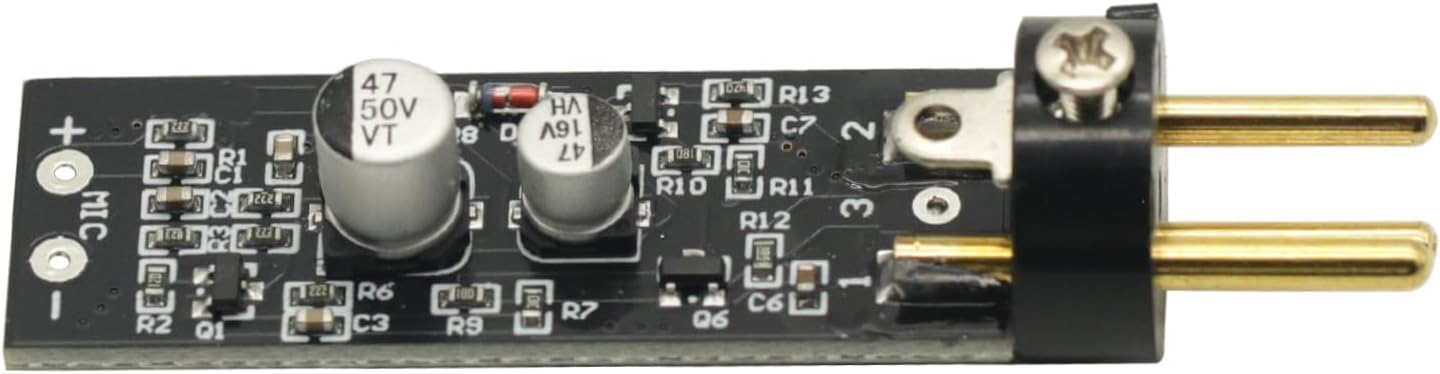
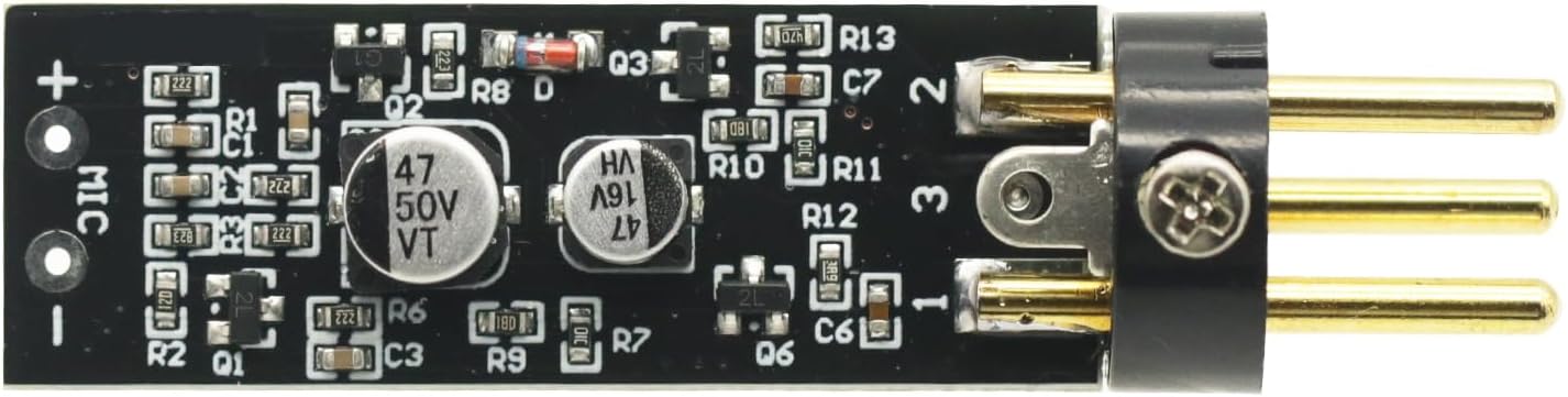
Fidio 1: Yi fidio pese a visual loriview of the Electret Microphone Amplifier Boards, showing their packaging and physical appearance. It demonstrates the compact size and how the electret microphone capsule connects to the board.
Atilẹyin ọja ati Support
For warranty information or technical support, please refer to the seller's policies on the platform where the product was purchased. Keep your purchase receipt as proof of purchase.