1. Ifihan
Thank you for choosing the Voltcraft VC-11 Digital Multimeter. This portable, Category III, 250V multimeter with a 2000-count display is designed for accurate electrical measurements in various applications. This manual provides essential information for safe operation, proper use, and maintenance of your device. Please read it thoroughly before use and keep it for future reference.
2. Alaye Aabo
WARNING: Electrical shock hazard. Improper use of this meter can cause damage, shock, injury, or death. Read and understand this manual before operating the meter.
- Always ensure the meter is in good working condition and the test leads are not damaged.
- Maṣe lo diẹ sii ju iwọn voltage, bi samisi lori mita, laarin awọn ebute tabi laarin eyikeyi ebute oko ati ilẹ.
- Lo iṣọra pupọ nigbati o ba n ṣiṣẹ pẹlu voltages above 25V AC RMS or 35V DC. These voltages duro a mọnamọna ewu.
- Máa yọ àwọn ìtọ́wò ìdánwò kúrò nínú àyíká náà kí o tó yí àwọn iṣẹ́ tàbí àwọn ìlà padà.
- Do not operate the meter with the battery cover removed or loosened.
- Adhere to local and national safety codes. Use personal protective equipment (PPE) such as approved safety glasses and electrically insulated gloves.
3. Ọja Ipariview
The Voltcraft VC-11 is a compact digital multimeter featuring a clear LCD display, a rotary function switch, and input jacks for test leads. It is designed for measuring DC/AC voltage, DC current, resistance, and includes diode and continuity test functions.
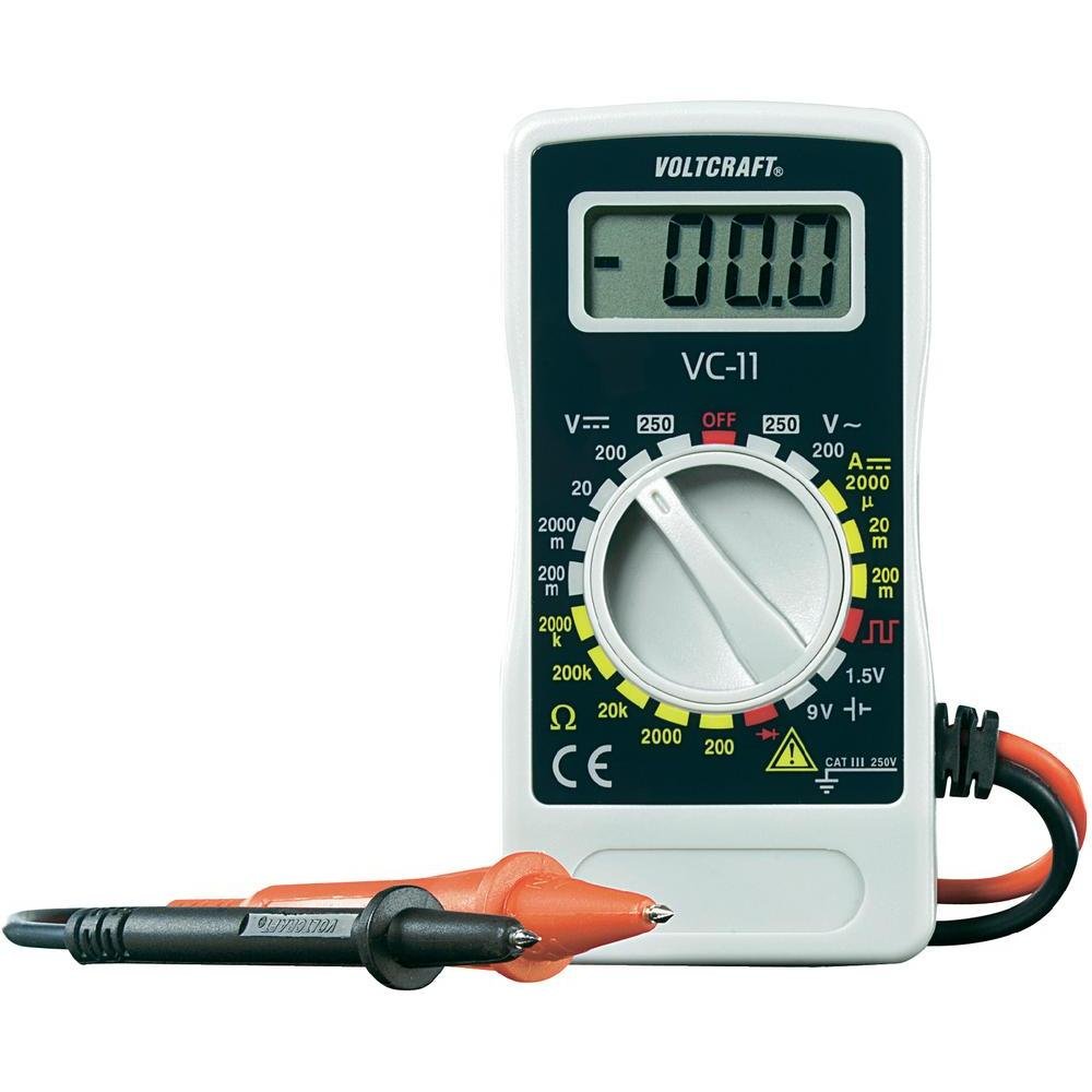
olusin 1: Iwaju view of the Voltcraft VC-11 Digital Multimeter with test leads connected. This image shows the LCD display, rotary switch, and input terminals.

olusin 2: Angled view of the Voltcraft VC-11 Digital Multimeter, highlighting the compact design and the CE marking.

Figure 3: The Voltcraft VC-11 Digital Multimeter shown with its test leads detached, illustrating the input ports.
3.1 irinše
- Ifihan LCD: Ṣe afihan awọn kika wiwọn, awọn ẹya, ati awọn afihan iṣẹ.
- Yiyi pada: A lo lati yan awọn iṣẹ wiwọn ati awọn sakani.
- Awọn Jacks ti nwọle: Ports for connecting the test leads (COM, VΩmA).
- Awọn itọsọna Idanwo: Red and black leads for connecting to the circuit under test.
4. Eto
4.1 Fifi sori batiri
The Voltcraft VC-11 requires a 9V battery for operation (not included). To install or replace the battery:
- Rí i dájú pé a ti pa multimeter náà, kí o sì yọ gbogbo àwọn ìtọ́wò ìdánwò kúrò.
- Wa ideri ibi ipamọ batiri naa ni ẹhin mita naa.
- Lo ẹ̀rọ ìdènà láti yọ ìdènà tí ó so ìbòrí batiri náà mọ́ kúrò.
- Fara yọ ideri kuro.
- So batiri 9V tuntun pọ mọ agekuru batiri naa, ki o wo polarity ti o tọ.
- Fi batiri sinu yara naa ki o si fi ideri naa pada, ki o si fi skru naa so o mọ.
4.2 Nsopọ Awọn itọsọna Igbeyewo
Always connect the black test lead to the 'COM' (common) jack. Connect the red test lead to the appropriate input jack based on the desired measurement:
- Fun Voltage (V), Resistance (Ω), Diode, and Continuity measurements, connect the red lead to the 'VΩmA' jack.
- For Current (A) measurements, connect the red lead to the 'VΩmA' jack (for mA range).
5. Awọn ilana Iṣiṣẹ
Before taking any measurement, ensure the test leads are correctly connected and the rotary switch is set to the desired function and range.
5.1 Idiwon DC Voltage (V=)
- Ṣeto iyipada iyipo si DC Vol ti o fẹtage (V=) range (e.g., 200mV, 2V, 20V, 200V, 250V). If the voltage is unknown, start with the highest range and decrease as needed.
- Connect the black test lead to the 'COM' jack and the red test lead to the 'VΩmA' jack.
- Connect the test probes in parallel across the component or circuit to be measured.
- Ka voltage iye lori ifihan LCD.
5.2 Iwọn AC Voltage (V~)
- Ṣeto iyipada iyipo si AC Vol ti o fẹtagìwọ̀n e (V~) (fún àpẹẹrẹ, 200V, 250V).
- Connect the black test lead to the 'COM' jack and the red test lead to the 'VΩmA' jack.
- Connect the test probes in parallel across the AC source or component.
- Ka voltage iye lori ifihan LCD.
5.3 Wiwọn Okun DC (A=)
- Set the rotary switch to the desired DC Current (A=) range (e.g., 2000µA, 20mA, 200mA).
- Connect the black test lead to the 'COM' jack and the red test lead to the 'VΩmA' jack.
- IKILO: To measure current, the meter must be connected in series with the circuit. Break the circuit and insert the meter.
- Connect the test probes in series with the circuit.
- Ka awọn ti isiyi iye lori LCD àpapọ.
5.4 Ìwọ̀n Àìdádúró (Ω)
- Rii daju pe iyika naa ti ni agbara ṣaaju idiwọn resistance.
- Set the rotary switch to the desired Resistance (Ω) range (e.g., 200Ω, 2kΩ, 20kΩ, 200kΩ, 2000kΩ).
- Connect the black test lead to the 'COM' jack and the red test lead to the 'VΩmA' jack.
- So àwọn ìwádìí ìdánwò pọ̀ mọ́ ara ohun èlò tí a fẹ́ wọ̀n.
- Ka iye resistance lori ifihan LCD.
5.5 Idanwo Diode
- Rí i dájú pé ẹ̀rọ náà kò ní agbára púpọ̀.
- Set the rotary switch to the Diode symbol (usually next to resistance).
- Connect the black test lead to the 'COM' jack and the red test lead to the 'VΩmA' jack.
- So ohun èlò pupa mọ́ anode, kí ohun èlò dúdú náà sì so mọ́ katódì ti diode náà. Ìfihàn náà yóò fi ohun èlò iwájú hàn.tage ju.
- Reverse the probes. The display should show 'OL' (Overload) for a good diode.
5.6 Igbeyewo Ilọsiwaju
- Rí i dájú pé ẹ̀rọ náà kò ní agbára púpọ̀.
- Set the rotary switch to the Continuity symbol (usually next to diode/resistance).
- Connect the black test lead to the 'COM' jack and the red test lead to the 'VΩmA' jack.
- So àwọn ìwádìí ìdánwò pọ̀ mọ́ ara wọn ní gbogbo àyíká tàbí ẹ̀yà ara wọn.
- If the resistance is below a certain threshold (typically 30-50Ω), the meter will emit an audible beep, indicating continuity.
6. Itọju
6.1 Ninu
Pa mita naa pẹlu ipolowoamp Aṣọ àti ọṣẹ ìfọṣọ díẹ̀. Má ṣe lo àwọn ohun ìfọṣọ tàbí àwọn ohun tí ó ń yọ́ omi. Rí i dájú pé mita náà gbẹ pátápátá kí o tó lò ó.
6.2 Batiri Rirọpo
When the battery symbol appears on the LCD display, the 9V battery needs to be replaced. Refer to section 4.1 for battery installation instructions.
7. Laasigbotitusita
| Isoro | Owun to le Fa | Ojutu |
|---|---|---|
| Ko si ifihan tabi baibai àpapọ | Ku tabi kekere batiri | Rọpo batiri 9V naa. |
| Awọn kika ti ko tọ | Incorrect function/range selected Poor test lead connection Damaged test leads | Select the correct function and range. Ensure test leads are firmly connected. Inspect and replace damaged test leads. |
| "OL" (Àfikún) tí a fi hàn | Measurement exceeds selected range Open circuit (for resistance/current) | Select a higher range. Check for breaks in the circuit. |
8. Awọn pato
- Brand: IWULO
- Nọmba awoṣe: VC11
- Olupese: IWULO
- Iwọn Ọja: Approximately 9.07 g (without packaging)
- Awọn iwọn idii: 14.8 x 8 x 3.6 cm
- Idiwon Ẹka: Nran III 250V
- Ifihan: 2000 Awọn iṣiro
- Orisun Agbara: Batiri 9V (ko si)
9. atilẹyin ọja Information
This product is covered by a standard manufacturer's warranty. Please refer to the warranty card included with your purchase or contact your retailer for specific terms and conditions. The warranty typically covers defects in materials and workmanship under normal use.
10. Onibara Support
For technical assistance, troubleshooting, or service inquiries, please contact Voltcraft customer support or your local distributor. Contact information can usually be found on the manufacturer's webaaye tabi lori apoti ọja.


