1. Ifihan
This manual provides essential instructions for the safe and effective use of your DT321B Digital Multimeter. This portable device is designed for measuring AC/DC voltage, DC current, resistance, and includes features for diode testing, continuity, battery testing, and transistor (hFE) measurements. Please read this manual thoroughly before operation and retain it for future reference.
2. Alaye Aabo
Always observe basic safety precautions when using this multimeter to reduce the risk of fire, electric shock, or personal injury.
- Maa ko waye voltage tabi lọwọlọwọ ti o kọja awọn opin ti a ti sọ tẹlẹ fun multimeter.
- Ensure the test leads are in good condition and properly connected before making any measurements.
- Never use the multimeter if it appears damaged or if the test leads are damaged.
- Ṣọ́ra nígbà tí o bá ń ṣiṣẹ́ pẹ̀lú voltages loke 30V AC RMS, 42V tente oke, tabi 60V DC. Awọn wọnyi ni voltages duro a mọnamọna ewu.
- Always disconnect power to the circuit under test before measuring resistance or continuity.
- Má ṣe lo multimeter níbi tí àwọn ohun afẹ́fẹ́ ń gbé.
- Rọpo awọn batiri nigbati ifihan batiri kekere ba han lati rii daju pe o peye awọn kika.
3. Ọja Ipariview
The DT321B Digital Multimeter features a clear LCD display and a rotary switch for selecting various measurement functions. Input jacks are provided for connecting test leads.

olusin 3.1: Iwaju view of the DT321B Digital Multimeter with key components labeled. The display shows numerical readings, the hold button freezes the current reading, and the rotary switch selects measurement functions. The '10A' jack is for high current measurements, 'COM' is the common ground, and 'VΩmA' is for voltage, resistance, and low current measurements.
The multimeter includes a blue backlight for improved visibility in low-light conditions and a data hold function to freeze the displayed reading.
4. Eto
4.1 Fifi sori batiri
The DT321B Digital Multimeter requires two 1.5V batteries (Type 7, typically AAA) for operation. To install or replace batteries:
- Rii daju pe multimeter ti wa ni pipa.
- Wa ideri iyẹwu batiri ni ẹhin ẹyọ naa.
- Tú àwọn skru tí ó wà ní ìpamọ́ náà kí o sì yọ ìbòrí náà kúrò.
- Insert the two 1.5V batteries, observing the correct polarity (+ and -) as indicated inside the compartment.
- Rọpo ideri ibi ipamọ batiri naa ki o si fi skru(s) so o mọ.
5. Awọn ilana Iṣiṣẹ
Before making any measurements, ensure the test leads are securely plugged into the correct input jacks.

Figure 5.1: The DT321B Multimeter with test probes connected. The black probe is connected to the 'COM' (common) jack, and the red probe is connected to the 'VΩmA' jack for most voltage, resistance, and low current measurements.
5.1 Idiwon DC Voltage (V–)
- Insert the red test lead into the 'VΩmA' jack and the black test lead into the 'COM' jack.
- Ṣeto iyipada iyipo si DC Vol ti o fẹtage (V–) range (e.g., 200m, 2, 20, 200, 1000V). If the voltage is unknown, start with the highest range and work downwards.
- So àwọn ìwádìí ìdánwò pọ̀ mọ́ ara wọn lórí ohun èlò tàbí àyíká tí a fẹ́ wọ̀n.
- Ka voltage iye lori ifihan LCD.
5.2 Iwọn AC Voltage (V∼)
- Insert the red test lead into the 'VΩmA' jack and the black test lead into the 'COM' jack.
- Ṣeto iyipada iyipo si AC Vol ti o fẹtage (V∼) range (e.g., 200, 750V).
- So àwọn ìwádìí ìdánwò pọ̀ mọ́ ara wọn lórí ohun èlò tàbí àyíká tí a fẹ́ wọ̀n.
- Ka voltage iye lori ifihan LCD.
5.3 Measuring DC Current (A–)
IKIRA: To avoid damage to the multimeter or the circuit, never connect the test leads in parallel across a voltage source when measuring current. Always connect in series.
- For currents up to 200mA, insert the red test lead into the 'VΩmA' jack. For currents up to 10A, insert the red test lead into the '10A MAX' jack. The black test lead always goes into the 'COM' jack.
- Set the rotary switch to the desired DC Current (A–) range (e.g., 200u, 2m, 20m, 200m, 10A).
- Ṣí àyíká tí a fẹ́ wọn ìsanwó náà kí o sì so multimeter náà pọ̀ mọ́ àyíká náà.
- Ka awọn ti isiyi iye lori LCD àpapọ.
5.4 Measuring Resistance (Ω)
IKIRA: Ensure the circuit under test is completely de-energized before measuring resistance.
- Insert the red test lead into the 'VΩmA' jack and the black test lead into the 'COM' jack.
- Set the rotary switch to the desired Resistance (Ω) range (e.g., 200, 2k, 20k, 200k, 2M).
- So àwọn ìwádìí ìdánwò pọ̀ mọ́ ara ohun èlò tí a fẹ́ wọ̀n.
- Ka iye resistance lori ifihan LCD.
5.5 Idanwo Diode
- Insert the red test lead into the 'VΩmA' jack and the black test lead into the 'COM' jack.
- Set the rotary switch to the diode symbol (→|).
- So ohun èlò pupa mọ́ anode, kí ohun èlò dúdú náà sì so mọ́ katódì ti diode náà. Ìfihàn náà yóò fi ohun èlò iwájú hàn.tage ju.
- Reverse the probes. The display should show 'OL' (open loop) for a good diode.
5.6 Igbeyewo Ilọsiwaju
- Insert the red test lead into the 'VΩmA' jack and the black test lead into the 'COM' jack.
- Set the rotary switch to the continuity symbol (♫).
- Connect the test probes across the circuit or component. If continuity exists (resistance below a certain threshold), the buzzer will sound.
5.7 Battery Testing (1.5V / 9V)
- Insert the red test lead into the 'VΩmA' jack and the black test lead into the 'COM' jack.
- Set the rotary switch to the '1.5V BATT' or '9V BATT' position.
- Connect the red probe to the positive terminal and the black probe to the negative terminal of the battery.
- Ka batiri voltage lori ifihan.
5.8 Transistor (hFE) Test
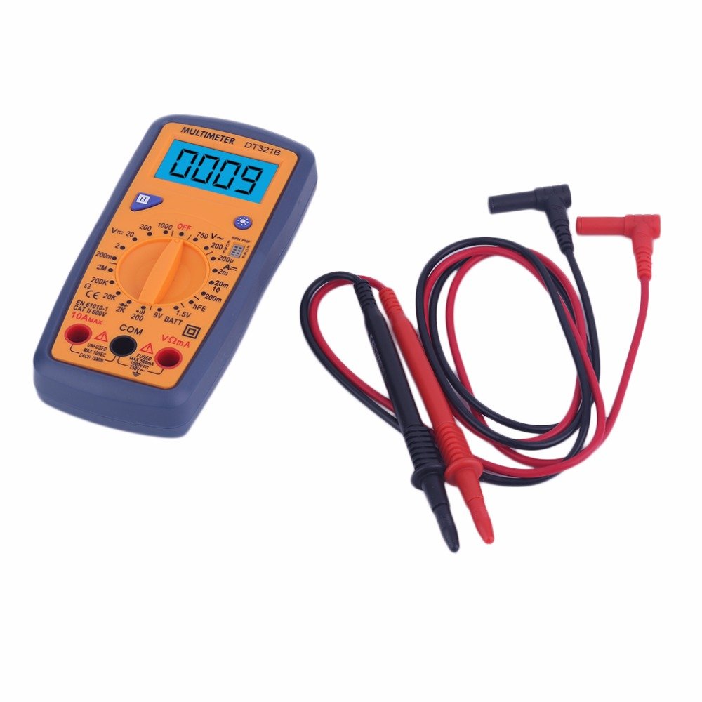
Figure 5.2: The DT321B Multimeter in use, with an inset showing a transistor being tested. The multimeter can measure the hFE (current gain) of NPN and PNP transistors.
- Set the rotary switch to the 'hFE' position.
- Identify the NPN or PNP type of the transistor.
- Insert the transistor leads (Emitter, Base, Collector) into the corresponding sockets in the 'hFE' test socket on the multimeter.
- Ka iye hFE lori iboju LCD.
5.9 Data idaduro Išė
Press the 'Hold' button to freeze the current reading on the display. Press it again to release the hold function and resume live readings.
5.10 Backlight Išė
The multimeter features a blue backlight. Press the backlight button (often integrated with the 'Hold' button or a separate button with a light symbol) to turn the backlight on or off for improved visibility.
6. Itọju
6.1 Ninu
Pa ọran naa pẹlu ipolowoamp cloth and a mild detergent. Do not use abrasives or solvents. Ensure the multimeter is completely dry before use.
6.2 Batiri Rirọpo
When the low battery symbol appears on the display, replace the batteries as described in Section 4.1. Remove batteries if the multimeter is not used for extended periods to prevent leakage.
7. Laasigbotitusita
- Ko si ifihan tabi ifihan ti ko lagbara: Ṣàyẹ̀wò fífi bátìrì sílẹ̀ kí o sì gba agbára. Rọpò bátìrì tí ó bá pọndandan.
- Awọn kika ti ko tọ: Ensure the rotary switch is set to the correct function and range. Check test lead connections. Verify the circuit under test is properly prepared (e.g., de-energized for resistance).
- 'OL' (Overload) displayed: Iye ti a wọn ju iwọn ti a yan lọ. Yipada si iwọn ti o ga julọ tabi ṣayẹwo fun iyipo ṣiṣi.
- No continuity buzzer: Ensure the multimeter is in continuity mode and the circuit is closed.
8. Awọn pato
| Wiwọn | Ibiti o | Yiye |
|---|---|---|
| DC Voltage | 200mV, 2V, 20V, 200V, 1000V | ± 0.5% |
| AC Voltage | 200V, 750V | ± 1.0% |
| DC Lọwọlọwọ | 200uA, 2mA, 20mA, 200mA, 10A | ± 1.8% |
| Atako | 200Ω, 2kΩ, 20kΩ, 200kΩ, 2MΩ | ± 1.0% |
Awọn Ni pato:
- Iwọn iboju LCD: 45x23mm
- Iwọn ọja: 160x76x32mm
- Ibi ti ina elekitiriki ti nwa: 2 x 1.5V batteries (Type 7 / AAA)
- Kekere Voltage Symbol Display: Bẹẹni
- Idaabobo Apọju: Bẹẹni
- Ṣíṣàwárí Díódì: Bẹẹni
- On-off Detection & Buzzer: Bẹẹni
- Iwari Agbara Batiri: 1.5V / 9V
- Transistor Detection (hFE): Bẹẹni
- Idaduro data: Bẹẹni
- Ifihan ina ẹhin: Bẹẹni
9. Atilẹyin ọja ati Support
Specific warranty and support information for the DT321B Digital Multimeter is not available in the provided product details. Please refer to the retailer or manufacturer's website for any applicable warranty terms or customer support contacts.


