1. Ifihan
This manual provides detailed instructions for the safe and effective use of the IDEAL Electrical 61-327 600V Manual Range Multimeter. This device is designed for measuring AC/DC voltage, resistance, continuity, diodes, and testing batteries. It is a CAT III 600V rated instrument suitable for various electrical testing applications.

Nọmba 1.1: Iwaju view of the IDEAL Electrical 61-327 Multimeter. This image displays the multimeter's main display, rotary dial, function buttons, and input jacks for test leads.
2. Alaye Aabo
IKILO: To avoid electric shock or personal injury, read, understand, and follow all safety information and instructions before using this multimeter. Keep this manual for future reference.
- Rí i dájú pé multimeter náà wà ní ipò tó dára kí o tó lò ó. Ṣe àyẹ̀wò àwọn ìtọ́sọ́nà ìdánwò fún ìbàjẹ́.
- Maṣe lo diẹ sii ju iwọn voltage, gẹ́gẹ́ bí a ṣe sàmì sí lórí mita náà, láàárín àwọn ebute tabi láàárín èyíkéyìí ebute ati ilẹ.
- Lo iṣọra nigbati o ba n ṣiṣẹ pẹlu voltages loke 30V AC RMS, 42V tente oke, tabi 60V DC. Awọn wọnyi ni voltages duro a mọnamọna ewu.
- Máa ge agbara Circuit náà nígbà gbogbo kí o sì máa tú gbogbo vol giga jádetage capacitors ṣaaju idanwo resistance, ilosiwaju, tabi diodes.
- Do not operate the meter with the case open or the battery cover removed.
- Rọpo awọn batiri lẹsẹkẹsẹ nigbati ifihan batiri kekere ba han lati rii daju pe o peye awọn kika.
- This multimeter is rated for CAT III 600V. Do not use it in environments exceeding this rating.
3. Awọn ẹya Ọja
The IDEAL Electrical 61-327 Multimeter offers a range of features designed for electrical professionals:
- UL Certified CAT III 600V: Ensures safety and reliability for AC/DC manual range measurements.
- Awọn Agbara Iwọn: Awọn iwọn AC/DC voltage, resistance, continuity, diodes, and tests batteries.
- Non-Olubasọrọ Voltage (NCV) Sensing: Ṣe awari AC voltage laisi ifọwọkan taara, ti o mu aabo pọ si.
- Ifihan Afẹyinti: Improves visibility in poorly lit environments.
- Built-in Probe Tip Holders: Allows for convenient and safer measurement by securing one lead.
- Hanging Strap Clip: Compatible with IDEAL hanging straps (sold separately, e.g., UMHS-757) for hands-free operation.
- Rugged Overmolding: Enhances grip and provides drop protection.
- Iṣe idaduro: Freezes the displayed reading for easier recording.
- Selectable Auto Power Off: Nfi aye batiri pamọ.
4. Irinše ati idari
Familiarize yourself with the main components and controls of your multimeter:

Nọmba 4.1: Iwaju view of the multimeter, highlighting the display, rotary switch, and function buttons. The display shows measurement values and indicators. The rotary switch selects measurement functions. Buttons include HOLD and Backlight.

Nọmba 4.2: Included test leads and AAA batteries. The red and black test leads are essential for making electrical measurements. The batteries power the device.

Nọmba 4.3: Ẹyìn view of the multimeter, showing the battery compartment cover and safety warnings. This view also illustrates the integrated test lead storage points.
5. Eto
5.1 Fifi sori batiri
The multimeter requires three (3) 1.5V AAA batteries for operation. To install or replace batteries:
- Rii daju pe multimeter ti wa ni pipa.
- Locate the battery compartment on the back of the meter (refer to Figure 4.3).
- Lo screwdriver lati tú dabaru ti o ni aabo ideri batiri naa.
- Yọ ideri batiri kuro.
- Insert three new 1.5V AAA batteries, observing the correct polarity (+/-) as indicated inside the compartment.
- Ropo ideri batiri ki o si Mu dabaru ni aabo.
5.2 Nsopọ Awọn itọsọna Igbeyewo
Always connect the black test lead to the "COM" (Common) input jack. Connect the red test lead to the "VΩ" input jack for voltage, resistance, continuity, and diode measurements. Ensure connections are firm.
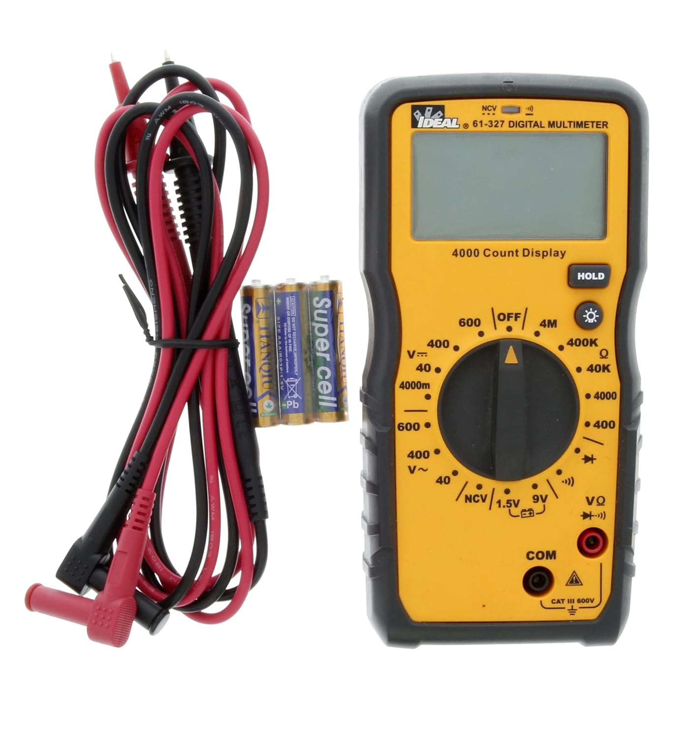
Nọmba 5.1: The multimeter shown with its test leads and batteries, ready for initial setup. The black lead connects to COM, and the red lead connects to VΩ.
6. Awọn ilana Iṣiṣẹ
This section details how to perform various measurements using the 61-327 Multimeter.
6.1 Iwọn AC / DC Voltage
- Yi iyipada iyipo pada si AC Vol ti o fẹtage (V~) or DC Voltage (V=) range. Select a range higher than the expected voltage.
- Connect the black test lead to the "COM" jack and the red test lead to the "VΩ" jack.
- So àwọn ìwádìí ìdánwò pọ̀ mọ́ àyíká tàbí èròjà tí o fẹ́ wọ̀n.
- Ka voltage iye lori ifihan.
6.2 Ìwọ̀n Àìdádúró (Ω)
- IKILO: Rí i dájú pé agbára ìṣiṣẹ́ náà ti dínkù, àti pé gbogbo àwọn capacitors ti tú jáde kí wọ́n tó wọn resistance.
- Turn the rotary switch to the desired Resistance (Ω) range.
- Connect the black test lead to the "COM" jack and the red test lead to the "VΩ" jack.
- So àwọn ìwádìí ìdánwò pọ̀ mọ́ ara ẹ̀rọ náà níbi tí a ti fẹ́ wọn resistance.
- Ka iye resistance lori ifihan.
6.3 Igbeyewo Ilọsiwaju
- IKILO: Rí i dájú pé agbára ìṣiṣẹ́ náà ti dínkù kí o tó ṣe ìdánwò ìtẹ̀síwájú.
- Turn the rotary switch to the Continuity (•))) position.
- Connect the black test lead to the "COM" jack and the red test lead to the "VΩ" jack.
- Fi ọwọ́ kan àwọn ohun ìdánwò náà sí àwọn ojú méjì tí o fẹ́ ṣàyẹ̀wò fún ìtẹ̀síwájú.
- Ohùn tí a lè gbọ́ fi hàn pé ó ń tẹ̀síwájú (ìdènà díẹ̀). Ìfihàn náà yóò fi iye ìdènà hàn.
6.4 Idanwo Diode
- IKILO: Ensure the circuit is de-energized before performing a diode test.
- Turn the rotary switch to the Diode (→|) position.
- Connect the black test lead to the "COM" jack and the red test lead to the "VΩ" jack.
- Connect the red test probe to the anode and the black test probe to the cathode of the diode.
- Awọn àpapọ yoo fi awọn siwaju voltagìsàlẹ̀. Yí àwọn ìwádìí padà; ìfihàn náà yẹ kí ó fi "OL" (Ṣíṣí Loop) hàn fún diode tó dára.
6.5 Battery Test (1.5V / 9V)
- Turn the rotary switch to the 1.5V or 9V battery test position.
- Connect the black test lead to the "COM" jack and the red test lead to the "VΩ" jack.
- Connect the red test probe to the positive terminal of the battery and the black test probe to the negative terminal.
- Ka batiri voltage lori ifihan.
6.6 Non-olubasọrọ VoltagÌmọ̀lára e (NCV)
Iṣẹ́ NCV gba láàyè láti rí i pé a ti lo AC voltage without direct contact with conductors.
- Yipada yiyi pada si ipo NCV.
- Move the top tip of the multimeter near the conductor or outlet to be tested.
- The meter will emit an audible tone and an illuminated red LED will flash when AC voltage is detected. The display may show "EF" or similar indication.

Nọmba 6.1: The multimeter being used to perform a Non-Contact Voltage (NCV) test near an electrical outlet. The display shows "EF" indicating voltage erin.
6.7 Using the HOLD Function
Tẹ bọtini "DÍDÁ" lati di kika lọwọlọwọ lori ifihan naa. Tẹ ẹ lẹẹkansi lati tu idaduro naa silẹ ki o si tun bẹrẹ awọn kika laaye.
6.8 Lilo Backlight
Press the backlight button (light bulb icon) to illuminate the display for better visibility in dark conditions. Press it again to turn off the backlight.
7. Itọju
7.1 Ninu
Pa mita naa pẹlu ipolowoamp asọ ati ìwọnba detergent. Maṣe lo awọn abrasives tabi awọn nkan ti o nfo. Rii daju pe mita naa ti gbẹ patapata ṣaaju lilo.
7.2 Batiri Rirọpo
Refer to Section 5.1 for instructions on battery installation and replacement. Always replace all three AAA batteries at the same time.
7.3 Igbeyewo asiwaju asiwaju
Regularly inspect test leads for any signs of damage, such as cuts, cracks, or frayed insulation. Replace damaged leads immediately to prevent electric shock.
8. Laasigbotitusita
| Isoro | Owun to le Fa | Ojutu |
|---|---|---|
| Mita ko ni agbara lori. | Awọn batiri ti o ku tabi ti ko tọ ti fi sori ẹrọ. | Check battery polarity; replace batteries (refer to Section 5.1). |
| "OL" (Overload) ni a fihan. | Wíwọ̀n náà ju ibi tí a yàn tàbí àyíká ṣíṣí lọ. | Select a higher range or check for an open circuit in the component/wiring. |
| Awọn kika ti ko pe. | Low battery, incorrect range selection, or damaged test leads. | Replace batteries, select appropriate range, inspect and replace test leads if damaged. |
| No continuity tone. | Ṣíṣí Circuit tàbí resistance gíga. | Verify the circuit is closed; check for breaks in wiring or components. |
9. Awọn pato
Key technical specifications for the IDEAL Electrical 61-327 Multimeter:
- Nọmba awoṣe: 61-327
- Iru wiwọn: Manual Range Digital Multimeter
- Iwọn Aabo: UL certified CAT III 600V AC/DC
- AC Voltage: Titi di 600V
- DC Voltage: Titi di 600V
- Atako: Up to 4MΩ (4000kΩ)
- Itesiwaju: Audible tone and resistance display
- Idanwo Diode: Bẹẹni
- Idanwo Batiri: 1.5V, 9V
- Non-Olubasọrọ Voltage (NCV): Bẹẹni
- Ifihan: Backlit, 4000 Count
- Orisun Agbara: 3 x 1.5V AAA Awọn batiri
- Agbara Aifọwọyi Paa: Yiyan
- Iṣe idaduro: Bẹẹni
- Awọn iwọn: Isunmọ 9.09 x 6.18 x 3.35 inches
- Ìwúwo: To 1.1 iwon
- Àwọ̀: Yellow
- Olupese: Ideal Industries

Nọmba 9.1: A comparison table of various IDEAL digital multimeters, including the 61-327, detailing their features and specifications. This table provides a quick overview of the 61-327's capabilities relative to other models.
10. Atilẹyin ọja ati Support
For warranty information, technical support, or service inquiries, please contact IDEAL Industries directly. Refer to the official IDEAL webAaye tabi apoti ọja fun awọn alaye olubasọrọ tuntun julọ.
Additional resources, including a downloadable PDF user manual, may be available on the IDEAL Store on Amazon tabi olupese ká osise webojula.


