1. Ifihan
This manual provides detailed instructions for the installation, configuration, and operation of the MokerLink 8-Port 2.5G PoE+ 6x10G SFP+ L3 Managed Switch. This device is designed to provide high-speed network connectivity with Power over Ethernet capabilities and advanced Layer 3 management features for various network environments.
The switch features 8 x 2.5 Gigabit PoE Ethernet ports, 2 x 10 Gigabit Ethernet ports, and 4 x 10 Gigabit SFP+ optical ports, offering flexible and high-bandwidth connectivity options.
2. Package Awọn akoonu
Verify the contents of your package. If any items are missing or damaged, please contact your vendor.
- MokerLink 8-Port 2.5G PoE+ 6x10G SFP+ L3 Managed Switch
- Okun agbara
- Ohun elo Rackmount
- Afowoyi Olumulo (iwe-ipamọ yii)
3. Ọja Ipariview
The MokerLink Managed Switch offers a robust solution for demanding network applications, combining high-speed data transfer with Power over Ethernet (PoE) functionality and comprehensive Layer 3 management.
3.1 Key Awọn ẹya ara ẹrọ
- 2.5G PoE Ports: 8 x 2.5Gigabit PoE Ethernet Ports (IEEE802.3bz compliant), supporting 10/100/1000M/2.5G adaptive speeds. Ports 1-8 support IEEE802.3AF/AT PoE protocol, auto-detecting compatible non-PoE devices. Maximum 30W output per port, with a total built-in power supply of 120W.
- 10Gbps Ports: 2 x 10G Ethernet Ports, backward compatible with 100M/1000M/2.5G/5Gbps rates, suitable for high-bandwidth uplink connections.
- SFP+ Awọn ibudo: 4 x 10G SFP+ optical ports supporting standard 10G/2.5G/1G adaptive modules (modules not included by default).
- L3 Managed Capabilities: Awọn atilẹyin Web/CLI management for device and port configuration. Includes Layer 3 routing (IPV4/IPV6 Management, Routes, ARP, Loopback Interface) and Layer 2 switching features (VLAN, ACL, QoS, Jumbo frame, DHCP, security, multicast, MAC address table, diagnosis, statistics, MSTP/RSTP/STP).
- Security & Diagnosis: Features AAA/802.1X/MAC-Based authentication, DoS anti-attack, dynamic ARP inspection, DHCP Snooping, IP Source Guard, Port Security, Protected Ports, storm control. Diagnostic tools include Console/RAM/Flash Logs, Port Mirroring, Ping, Traceroute, Port Tests, UDLD Protocol.
- Ìṣàkóso Rọrùn: Supports Telnet/SSH/SNMP, Firmware Upgrade, Configuration File Download/Upload.
- Apẹrẹ: Metal case, desktop/wall-mounting design, industrial-grade fan for heat dissipation.
3.2 Ìṣètò Pánẹ́lì Iwájú
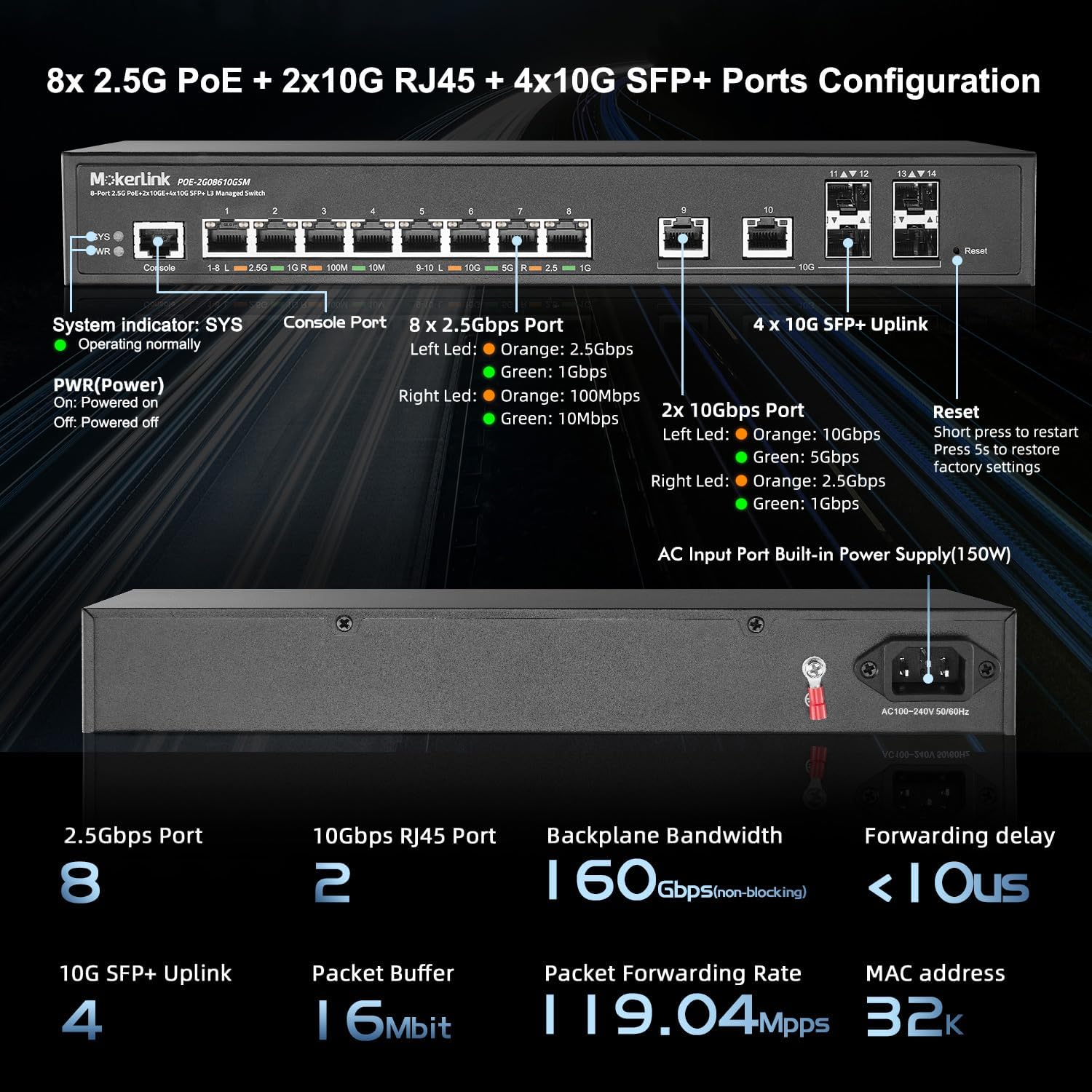
olusin 1: Iwaju Panel Loriview. This image displays the front panel of the switch, highlighting the Console Port, 8x 2.5Gbps PoE ports (1-8), 2x 10Gbps RJ45 ports (9-10), 4x 10G SFP+ Uplink ports (11-14), System (SYS) and Power (PWR) indicators, and the Reset button.
- Atọka SYS: Indicates system operating status. Blinking rapidly may indicate an issue.
- Atọka PWR: Indicates power status. On for powered, Off for powered off.
- Ibudo Kọnsole: RJ45 port for CLI management.
- 2.5Gbps Ports (1-8): 8x 2.5 Gigabit Ethernet ports with PoE+ support. LEDs indicate link speed (Orange: 2.5Gbps, Green: 1Gbps, Off: 100Mbps).
- 10Gbps Ports (9-10): 2x 10 Gigabit Ethernet RJ45 ports. LEDs indicate link speed (Orange: 10Gbps, Green: 5Gbps, Off: 2.5Gbps/1Gbps).
- SFP+ Uplink Ports (11-14): 4x 10 Gigabit SFP+ slots for fiber optic connections.
- Bọtini atunto: Press briefly to restart. Press and hold for 5 seconds to restore factory settings.
3.3 Ru Panel Ìfilélẹ
olusin 2: Ru Panel Loriview. This image shows the rear panel of the switch, featuring the AC Input Power Port (150W) for connecting the power cord.
- AC Input Power Port: Connects to the included power cord for AC power supply (100-240V, 50/60Hz).
4. Eto ati fifi sori
Follow these steps to properly install and set up your MokerLink Managed Switch.
4.1 Awọn iṣọra aabo
- Rii daju pe ipese agbara voltage matches the switch's requirements.
- Maṣe ṣe idiwọ awọn ṣiṣi eefin.
- Avoid exposing the switch to water or excessive humidity.
- Do not open the switch casing. Refer servicing to qualified personnel.
4.2 Fifi sori ti ara
The switch can be installed on a desktop or mounted in a rack.
Fifi sori tabili
Place the switch on a flat, stable surface. Ensure adequate space around the switch for ventilation.
Rackmount fifi sori
Use the provided rackmount kit to install the switch into a standard 19-inch equipment rack. Secure the mounting brackets to the sides of the switch, then attach the switch to the rack using appropriate screws.

Figure 3: Rackmount Installation. This image illustrates multiple MokerLink switches mounted within a standard server rack, demonstrating the rackmount capability.
4.3 Nsopọ Awọn okun Nẹtiwọọki
Connect your network devices to the appropriate ports on the switch.
- 2.5G PoE Ports (1-8): Use CAT5e, CAT6, or CAT7 Ethernet cables for connecting devices such as IP cameras, wireless access points, IP phones, or other network devices. These ports provide both data and power for PoE-compatible devices.
- 10G RJ45 Ports (9-10): Use CAT6 (up to 55m), CAT6a, or CAT7 (up to 100m) Ethernet cables for high-speed connections to servers, other switches, or devices requiring 10 Gigabit speeds.
- 10G SFP+ Awọn ibudo (11-14): Insert compatible 1G/10G SFP+ optical modules into these slots, then connect fiber optic cables for high-speed fiber uplinks or connections to other SFP+ enabled devices.

Figure 4: 2.5Gbps Port Connectivity. This image shows the 2.5Gbps ports (1-8) and indicates compatibility with CAT5e, CAT6, and CAT7 cables for connecting devices like WiFi APs, NAS, and Workstations.

Figure 5: 10Gbps Port Connectivity. This image details the 10Gbps RJ45 ports (9-10) and SFP+ ports (11-14), specifying compatible cable types (CAT6, CAT6a, CAT7) and adaptive SFP modules for connecting servers and core switches.
4.4 Agbara Lori Yipada
Connect the power cord to the AC Input Power Port on the rear of the switch and then to a power outlet. The PWR indicator on the front panel should illuminate, and the SYS indicator will begin to blink as the system boots up.
5. Ṣiṣẹ Yipada
The MokerLink Managed Switch offers various methods for configuration and management.
5.1 Initial Access and Management
Yipada le ti wa ni isakoso nipasẹ a Web-based Graphical User Interface (GUI) tabi Command Line Interface (CLI).
Web Interface (GUI) Access
- So kọmputa kan pọ si eyikeyi awọn ebute oko oju omi Ethernet ti yipada.
- Configure your computer's IP address to be in the same subnet as the switch's default IP address (e.g., if the switch is 192.168.2.1, set your computer to 192.168.2.X, where X is not 1, with subnet mask 255.255.255.0).
- Ṣii a web browser and enter the default IP address of the switch: 192.168.2.1
- Enter the default username and password: abojuto / abojuto
- Upon successful login, you will access the switch's management interface. It is highly recommended to change the default password immediately for security.
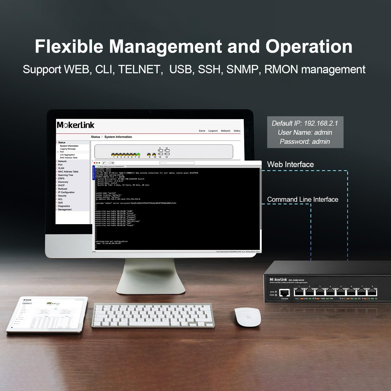
Figure 6: Flexible Management Options. This image displays both the web interface and command-line interface (CLI) for managing the MokerLink switch, along with the default IP address, username, and password.
Command Line Interface (CLI) Access
Connect to the Console port using an RJ45-to-serial cable and a terminal emulator (e.g., PuTTY, Tera Term) with the following settings:
- Oṣuwọn Baud: 115200
- Data Bits: 8
- Parity: Ko si
- Duro Awọn idinku: 1
- Iṣakoso sisan: Ko si
Login with the default username and password (admin/admin).
5.2 Iṣẹ́ PoE
The 2.5G ports (1-8) support IEEE 802.3af/at Power over Ethernet standards. The switch automatically detects and provides power to compatible Powered Devices (PDs).

Figure 7: PoE+ Support. This diagram illustrates how the switch provides power to PoE devices (IP Camera, Wireless AP, IP Phone) while also connecting to non-PoE devices (Router, Computer, NVR) for data only.
- Max 30W per PoE port.
- Total PoE Power Budget: 120W.
- The switch supplies 48V output voltage to PoE devices.
- For ports connected to non-PoE devices, it is recommended to disable PoE on those specific ports via the management interface to prevent potential issues.
5.3 Layer 2 and Layer 3 Features
The switch provides a comprehensive set of Layer 2 and Layer 3 features for advanced network management.

Figure 8: Layer 3 Managed Features. This image highlights various software features including VLAN, QoS, LACP, IGMP, ACL, DHCP, SNMP, Route, and Security.
VLAN (Nẹ́tíwọ́ọ̀kì Àgbègbè Fíìmù)
VLANs allow you to segment your network into logical broadcast domains, improving security and performance. The switch supports 802.1Q Tag-based VLANs.

Figure 9: VLAN Configuration. This diagram illustrates how 802.1Q Tag-based VLANs can segregate network traffic for different device types (e.g., IP cameras, wireless APs, IP phones) without requiring separate physical equipment.
QoS (Didara Iṣẹ)
QoS allows you to prioritize network traffic, ensuring critical applications (like voice or video) receive sufficient bandwidth and low latency.

Figure 10: QoS Prioritization. This diagram shows how QoS prioritizes different types of network traffic, such as high priority for audio, medium for video, and low for general data, to reduce packet loss and latency.
Link Aggregation (LACP)
LACP (Link Aggregation Control Protocol) allows you to group multiple physical links into a single logical link, increasing bandwidth and providing redundancy.

Figure 11: Link Aggregation. This diagram illustrates how LACP combines multiple Ethernet connections between the MokerLink switch and other devices (like another switch or a NAS) to increase bandwidth and improve resilience.
Layer 3 Ipa ọna
The switch supports IPV4/IPV6 routing, ARP, and Loopback Interface management, enabling inter-VLAN routing and more complex network topologies.
Aabo Awọn ẹya ara ẹrọ
Implement security measures such as AAA/802.1X/MAC-Based authentication, DoS anti-attack, dynamic ARP inspection, DHCP Snooping, IP Source Guard, Port Security, Protected Ports, and storm control to protect your network.
6. Itọju
Regular maintenance ensures optimal performance and longevity of your switch.
6.1 Igbesoke Famuwia
Firmware updates can provide new features, performance improvements, and security patches. Refer to the management interface for firmware upgrade options. It is recommended to download firmware from the official MokerLink support channels. As of current information, firmware updates may not be publicly available on the manufacturer's website, and direct contact might be required.
6.2 Iṣeto ni Afẹyinti ati Mu pada
Regularly back up your switch configuration to prevent data loss. The management interface (Web GUI or CLI) provides options to download the current configuration file and upload a saved configuration file.
CLI Command Example: copy running-config startup-config to save current configuration.
6.3 Ayika riro
Ensure the switch is operated within its specified temperature and humidity ranges. The industrial-grade fan assists with heat dissipation, but proper airflow around the unit is crucial.

Figure 12: Design and Efficiency. This image highlights the switch's features such as Energy Efficient Ethernet (EEE), durable metal casing, and overall energy-saving design, with arrows indicating airflow for cooling.
7. Laasigbotitusita
Abala yii n pese awọn ojutu si awọn ọran ti o wọpọ ti o le ba pade.
7.1 No Power / System Indicator Off
- Verify the power cord is securely connected to both the switch and the power outlet.
- Rii daju pe iṣan agbara jẹ iṣẹ-ṣiṣe.
- Ṣàyẹ̀wò ẹ̀rọ ìpèsè agbára fún èyíkéyìí ìbàjẹ́ tí ó hàn gbangba.
7.2 No Link Light / No Connectivity
- Ṣàyẹ̀wò ìsopọ̀ okùn Ethernet ní ìpẹ̀kun méjèèjì. Gbìyànjú okùn mìíràn.
- Rii daju pe ẹrọ ti a ti sopọ ti wa ni titan ati pe o nṣiṣẹ ni deede.
- Verify the port status in the switch's management interface.
- For SFP+ ports, ensure the SFP+ module is correctly inserted and compatible, and the fiber cable is intact.
7.3 Poe Device Ko Alagbara Lori
- Confirm the connected device is PoE-compatible (IEEE 802.3af/at).
- Check the PoE status of the port in the switch's management interface. Ensure PoE is enabled for that port.
- Verify the power requirements of the PD do not exceed 30W per port or the total 120W budget.
- If connecting a non-PoE device to a PoE port, it is recommended to disable PoE on that port to prevent potential damage to the non-PoE device.
7.4 Network Performance Issues
- Check for network loops. The switch supports loop detection to help identify and resolve these.
- Utilize QoS settings to prioritize critical traffic.
- Review port statistics and logs in the management interface for errors or high utilization.

Figure 13: Loop Detection. This diagram illustrates how the loop detection feature helps identify and remove network loops between switches or devices, preventing network slowdowns or outages.
7.5 Ntun to Factory aseku
If you forget the login credentials or encounter persistent configuration issues, you can reset the switch to its factory default settings. With the switch powered on, press and hold the Bọtini atunto on the front panel for approximately 5 seconds until the SYS LED blinks rapidly, then release. The switch will reboot with default settings.
8. Awọn pato
| Ẹya ara ẹrọ | Apejuwe |
|---|---|
| Nọmba awoṣe | 8x2.5G POE + 6x10G SFP Managed |
| Ni wiwo Iru | PoE, SFP+ |
| Nọmba ti Ports | 8x 2.5G PoE, 2x 10G Ethernet, 4x 10G SFP+ |
| Poe Standard | IEEE 802.3af / ni |
| Lapapọ Poe Power isuna | 120W |
| Data Gbigbe Oṣuwọn | 10 Gigabits Per Second (max) |
| Bandiwidi Backplane | 160 Gbps (ti kii ṣe idena) |
| Packet saarin | 16 Mbit |
| Packet Ndari Oṣuwọn | 119.04 Mpps |
| Mac adirẹsi Table Iwon | 32K |
| Isakoso | Web GUI, CLI (Console, Telnet, SSH), SNMP |
| Layer Features | L2 (VLAN, QoS, LACP, STP), L3 (Static Routing, ARP) |
| Awọn iwọn | 14.25 x 11.5 x 3.27 inches |
| Iwọn Nkan | 5.06 iwon |
| Ohun elo ọran | Irin |
| Àwọ̀ | Dudu |
| Awọn irinše to wa | 2.5G POE Switch, Power Cord, Rackmount Kit |
9. Atilẹyin ọja ati Support
MokerLink products typically come with a standard manufacturer's warranty. Please refer to the product packaging or the official MokerLink webAaye fun pato awọn ofin ati ipo atilẹyin ọja.
For technical support, product inquiries, or to obtain the latest firmware updates, it is recommended to contact MokerLink directly through their official support channels. As noted in some user reviews, direct support may be the primary method for obtaining detailed documentation or firmware beyond what is included with the product.
For general information, you may visit the MokerLink Store on Amazon.


