1. Ifihan
This manual provides comprehensive instructions for the installation, configuration, and operation of the CUIPPWRJ GEP-F722-BT-HD V2 Flight Controller. Designed for DIY RC quadcopters and freestyle drones, this flight controller features an STM32F722RET6 MCU, 3-6S LiPo compatibility, and a Type-C USB connector. Please read this manual thoroughly before use to ensure proper functionality and safety.
2. Awọn pato
- MCU: STM32F722RET6
- IMU: 42688-P (SPI)
- Apoti Dudu: 512MB onboard SD card
- Asopọ USB: Iru-C
- OSD: OSD with AT7456E chip
- Ṣiṣe BEC: 5V 3A / 12V 3A
- Sisẹ: Integrated filtering
- Firmware: GEPRCF722-BT-HD
- Iwọn: 36x36mm, φ4mm hole becomes φ3mm after using grommets
- Iṣagbewọle Voltage: LiPo 3-6S
- Àwọn UART: 5
- Awọn iwọn idii: 1.18 x 0.79 x 0.39 inches
- Ìwọ̀n Nkan: 14.1 iwon
3. Key Awọn ẹya ara ẹrọ
- Advanced STM32F722RET6 processor for superior performance.
- Wide igbewọle voltage compatibility (3-6S LiPo) for diverse drone setups.
- Integrated 5V 3A and 12V 3A BEC outputs for powering peripherals.
- Onboard 512MB black box for flight data logging.
- Type-C USB connector for convenient configuration.
- Built-in OSD with AT7456E chip for on-screen display.
- Compact 36x36mm size with φ4mm to φ3mm mounting holes.
4. Package Awọn akoonu
Apo naa pẹlu:
- 1 x CUIPPWRJ GEP-F722-BT-HD V2 Flight Controller
5. Pinout Diagram and Connections
Refer to the diagram below for the pinout and connection points of the GEP-F722-BT-HD V2 Flight Controller. Proper connection is essential for safe and reliable operation.
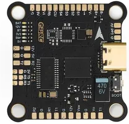
Apejuwe aworan: A oke-isalẹ view of the black GEP-F722-BT-HD V2 Flight Controller board. It features various solder pads and connectors around its perimeter. Key labels visible include BAT, 12V, 5V, 3V3, G (Ground), T (Transmit), R (Receive) for UARTs, S1-S4 for motor outputs, and a Type-C USB port on the right side. A "BOOT" button and a 470 6V capacitor are also visible near the USB port. The "GEPRC" logo is printed on the board.
5.1. Pin Awọn apejuwe
| Aami Pin | Apejuwe |
|---|---|
| BAT | Batiri Voltage Input (3-6S LiPo) |
| 12V | 12V BEC Output (3A max) |
| 5V | 5V BEC Output (3A max) |
| 3V3 | 3.3V Ijade |
| G | Ilẹ |
| BT | Bluetooth (if applicable, check firmware) |
| S1-S4 | Motor Signal Outputs (PWM) |
| R1, T1 | UART1 Receive and Transmit |
| R2, T2 | UART2 Receive and Transmit |
| R3, T3 | UART3 Receive and Transmit |
| R5, T5 | UART5 Receive and Transmit |
| CU | Input Sensọ lọwọlọwọ |
| Vsw | Video Switch (if applicable) |
| Vo | Ijade fidio |
| Bọọlu | Bootloader Button (for DFU mode) |
| Led V | LED Strip Voltage Ijade |
6. Eto ati iṣeto ni
6.1. Fifi sori ti ara
- Mount the flight controller onto your drone frame using the provided grommets to reduce vibrations. Ensure the arrow on the FC points towards the front of the drone.
- Connect motor ESC signal wires to the corresponding S1-S4 pads.
- Connect the battery power lead (VBAT) to the BAT and G pads.
- Connect your receiver (e.g., SBUS, CRSF, PPM) to an available UART (e.g., R2/T2).
- Connect your VTX (Video Transmitter) to a 5V or 12V output, Ground, and Video Out (Vo) pad.
- Connect your FPV camera to a 5V or 12V output, Ground, and Video In (Vsw or similar, depending on setup).
- Connect any other peripherals (GPS, LED strips) to appropriate UARTs or power outputs.
6.2. Firmware Flashing and Configuration
- Ṣe igbasilẹ ati fi sọfitiwia Betaflight Configurator tuntun sori kọmputa rẹ.
- Connect the flight controller to your computer using a Type-C USB cable.
- If the flight controller is not recognized, you may need to install DFU drivers. Press and hold the BOOT button while plugging in the USB cable to enter DFU mode.
- In Betaflight Configurator, select the correct firmware target (GEPRCF722-BT-HD) and flash the latest stable firmware.
- After flashing, connect to the flight controller and perform initial configuration:
- Calibrate the accelerometer.
- Configure UARTs for your receiver, VTX, GPS, etc.
- Set up motor protocols (e.g., DShot).
- Configure OSD elements.
- Perform a full backup of your configuration.
7. Awọn ilana Iṣiṣẹ
Once the flight controller is installed and configured, follow these steps for operation:
- Rii daju pe gbogbo awọn asopọ wa ni aabo ati pe o tọ.
- Power on your radio transmitter.
- Connect the LiPo battery to your drone. The flight controller will power up.
- Verify that your FPV feed is clear and OSD information is displayed correctly.
- Arm the drone using your configured arming switch on the transmitter.
- Perform pre-flight checks, including motor direction and control surface response.
- Fly responsibly and within legal limits.
- After flight, disarm the drone and disconnect the LiPo battery.
8. Itọju
- Regularly inspect solder joints for cracks or cold joints.
- Keep the flight controller clean and free from dust, dirt, and moisture.
- Avoid exposing the board to extreme temperatures or static discharge.
- Periodically check for and update to the latest stable firmware versions.
- Ensure all mounting screws are secure but not overtightened.
9. Laasigbotitusita
- Ko si Agbara: Check battery connection, polarity, and ensure the battery is charged. Inspect for shorts.
- Not Connecting to Betaflight: Ensure correct drivers are installed. Try a different USB cable or port. Enter DFU mode by holding the BOOT button while plugging in.
- Àwọn ẹ́rọ tí kò ń yípo: Verify ESC connections, motor protocol in Betaflight, and ensure the drone is armed. Check motor direction.
- No FPV Feed: Check camera and VTX connections, power to VTX/camera, and ensure correct video input/output settings in Betaflight OSD.
- Ọkọ ofurufu aiduroṣinṣin: Re-check mounting for vibrations, recalibrate accelerometer, verify PID settings, and ensure propellers are undamaged and balanced.
10. Atilẹyin ọja ati Support
Fun alaye atilẹyin ọja ati atilẹyin imọ-ẹrọ, jọwọ tọka si osise olupese webojula tabi kan si alagbata rẹ. Jeki ẹri rira rẹ fun eyikeyi awọn ibeere atilẹyin ọja.


